Service Manuals, User Guides, Schematic Diagrams or docs for : JBL Audio DSC-400 DSC-400
<< Back | HomeMost service manuals and schematics are PDF files, so You will need Adobre Acrobat Reader to view : Acrobat Download Some of the files are DjVu format. Readers and resources available here : DjVu Resources
For the compressed files, most common are zip and rar. Please, extract files with Your favorite compression software ( WinZip, WinRAR ... ) before viewing. If a document has multiple parts, You should download all, before extracting.
Good luck. Repair on Your own risk. Make sure You know what You are doing.
Image preview - the first page of the document

>> Download DSC-400 documenatation <<
Text preview - extract from the document
                                                                                  Service Bulletin
Service bulletin # JBL2002-002                                                                              February 2002

     To:             all JBL Service Centers

     Models:         DSC 400 ( DSC100 )

     Subject:        Bad picture quality In RGB


In the event, you receive a DSC400 ( DSC100 ) with the complaint: In RGB mode, the picture has poor resolution or there are
pixels in the picture, do following modification.

Part needed:         One resistor 75 (or two 150 in parallel)
                     One Transistor BC 548, part no. 3614-5925

The modification is only on the video board.

1.     Remove the top cover of the DSC 100
2.     Release the Video board (4 screws) and place the board with the solder side up.
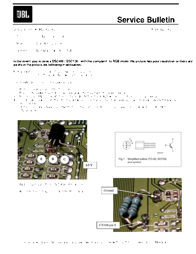
3.     Remove the SMD resistor R1178 (on the PCB , R1176, the 8 digit number is half covered by a solder point)
4.     Use the two solder points from the resistor to place the transistors emitter and base, see the picture below for placing
       the collector.
       On the schematics, Base on output from IC109 pin 20, collector on 3.3V supply (see on diode D103), Emitter on
       CN108 pin 8.


                        E       B       C
                                                         3.3 V


5.     Add a 75 resistor from CN 108 pin 8 to ground.

6.     Assemble the unit again and test the RGB mode                   Ground


                                                                    CN108 pin 8


           Harman International SNC - Harman Consumer International 2, route de Tours 72500 Ch
◦ Jabse Service Manual Search 2024 ◦ Jabse Pravopis ◦ onTap.bg ◦ Other service manual resources online : Fixya ◦ eServiceinfo