Service Manuals, User Guides, Schematic Diagrams or docs for : JVC Car Audio KS-FX725R
<< Back | HomeMost service manuals and schematics are PDF files, so You will need Adobre Acrobat Reader to view : Acrobat Download Some of the files are DjVu format. Readers and resources available here : DjVu Resources
For the compressed files, most common are zip and rar. Please, extract files with Your favorite compression software ( WinZip, WinRAR ... ) before viewing. If a document has multiple parts, You should download all, before extracting.
Good luck. Repair on Your own risk. Make sure You know what You are doing.
Image preview - the first page of the document
>> Download KS-FX725R documenatation <<
Text preview - extract from the document
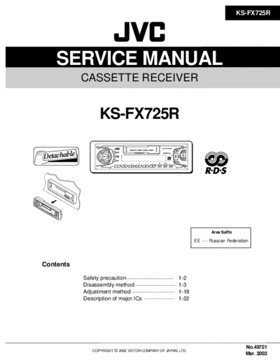
KS-FX725R
SERVICE MANUAL
CASSETTE RECEIVER
KS-FX725R
DISP
DAB
TP
RDS
PTY
7 8 9 10 11 12 MO
Area Suffix
EE ---- Russian Federation
Contents
Safety precaution 1-2
Disassembly method 1-3
Adjustment method 1-18
Description of major ICs 1-22
No.49721
COPYRIGHT 2002 VICTOR COMPANY OF JAPAN, LTD.
Mar. 2002
KS-FX725R
Safety precaution
! Burrs formed during molding may be left over on some parts of the chassis. Therefore,
pay attention to such burrs in the case of preforming repair of this system.
1-2
KS-FX725R
Disassembly method
Removing the front panel assembly
(See Fig.1)
1. Press the eject button in the lower right part of the
front panel. Remove the front panel assembly from
the body.
Front panel assembly
Eject button
Fig.1
Joint a
Removing the front chassis assembly
(See Fig.2 , 3)
Prior to performing the following procedure, remove
the front panel assembly.
1. Release the four joints a on both sides of the front
chassis assembly and remove the front chassis
assembly toward the front.
Joint a
Front chassis assembly
Fig.2
Heat sink Joint a
Joint a Front chassis
assembly
Fig.3
1-3
KS-FX725R
Removing the heat sink (See Fig.4)
1. Remove the three screws A on the left side of the
body.
Heat sink
A A
Fig.4
Joint b
Removing the bottom cover
(See Fig.5 , 6) Bottom cover
Prior to performing the following procedure, remove
the front panel assembly, the front chassis assembly
and the heat sink.
1. Turn over the body and unjoint the five joints b with
the bottom cover and the body using a screwdriver.
Joint c
CAUTION: When disengaging the joint c using a Joint b
screwdriver, do not damage or break the Rear panel
board.
Fig.5
Joint b
Bottom cover
Joint c
Joint b Rear panel
Fig.6
1-4
KS-FX725R
Removing the main board B C
(See Fig.7 , 8)
Prior to performing the following procedure, remove
the front panel assembly, the front chassis assembly,
the heat sink and the bottom cover. D
D
1. Remove the screw B, the three screws C and the
two screws D attaching the rear bracket on the back
of the body. Remove the rear panel. Rear panel
C
Fig.7
2. Remove the two screws E attaching the main board
on the bottom of the body. Disconnect connector
CP401 on the main board in the direction of the
Main board
arrow.
E E
CP401
Fig.8
Removing the cassette mechanism section Cassette mechanism section
(See Fig.9) F F Top chassis
Prior to performing the following procedure, remove
the front panel assembly, the front chassis assembly,
the heat sink, the bottom cover and the main board.
1. Remove the four screws F attaching the cassette
mechanism section on the back of the top chassis.
F F
Fig.9
1-5
KS-FX725R
Removing the control switch board
(See Fig.10 ~ 12)
Prior to performing the following procedure, remove
the front panel assembly.
1. Remove the four screws G attaching the rear cover G G
on the back of the front panel assembly.
2. Unjoint the ten joints d with the front panel and the
rear cover.
3. Remove the control switch board on the back of the
front panel.
G Rear cover G
Fig.10
Joint d
Front panel
Joint d
Joint d
Joint d
Rear cover
Fig.11
Front panel
Control switch board
Fig.12
1-6
KS-FX725R
REFERENCE: Prior to performing the following
procedures, turn the mode gear on the
bottom of the body until the respective part
comes to the EJECT position (Refer to
Fig.1).
Removing the reinforce bracket
(See Fig.1 and 2) Mode gear
1. Remove the screw A attaching the reinforce bracket
on the bottom of the body. Reinforce bracket
2. To release joint a, turn and detach the reinforce A
bracket from the side bracket assembly as shown in Fig.1
Fig.2
Removing the cassette guide (See Fig.3)
1. Turn the mode gear to set to RVS play or Joint a
subsequent mode.
2. Remove the cassette guide from the main chassis
while releasing each two joint tabs b in the direction Reinforce bracket
of the arrow.
Removing the head board (See Fig.4)
1. Remove the screw B on the upper side. Unsolder
the wires on the under side of the head board, if
necessary. Fig.2
REFERENCE: When reassembling, twist the wires by
turning the head board twice remarked c
and pass through the notch d as shown
in Fig.4.
Head board
Soldering
B
Cassette guide Head board
notch d
Tab b c
Tab b
Fig.3 Fig.4
1-7
KS-FX725R
Removing the load arm (See Fig.5) Load arm
1. Remove the E-washer attaching the load arm.
2. Move the load arm in the direction of the arrow and
release the joint e on the cassette catch.
E-washer
Joint e
Fig.5
Cassette holder assembly
Removing the cassette hanger assembly /
Boss g
cassette holder (See Fig.6 to 9) Side bracket Cassette hanger
assembly
1. Check the mode is set to EJECT. Push down the Boss g
front part of the cassette holder and move in the
direction of the arrow to release the joint f. Joints f
2. Move the rear part of the cassette hanger assembly
in the direction of the arrow to release it from the two
joint bosses g.
3. Release the holder stabilizer spring from the hooks h Cassette holder assembly
and i, then pull out from the cassette hanger Fig.6
assembly. Cassette hanger assembly
Cassette stabilizer spring
4. Bring up the rear side of the cassette hanger
assembly to release the joint j and k.
5. Pull out the cassette catch from the cassette hanger
assembly.
Hook i
Hook h
Fig.7
Cassette hanger assembly
Cassette holder
assembly Cassette catch
Cassette holder assembly
Cassette hanger assembly
Hook j
Hook k
Fig.8 Fig.9
1-8
KS-FX725R
Removing the side bracket assembly
Side bracket assembly
(See Fig.10 to 12)
Joint l
1. Remove the screw C attaching the side bracket
assembly. Joint m
2. Detach the front side of the side bracket assembly
upward and pull out forward to release the joint l and
m in the rear. C
CAUTION: When reassembling, make sure that the
boss n of the main chassis is set in the
notch of the load rack under the side
bracket assembly. Do not reattach the
load rack on the boss n.
Side bracket assembly
Fig.10
CAUTION: After reattaching the side bracket
assembly, confirm operation.
Side bracket assembly
Joint l
Joint m
Load rack
Boss n
Boss n Fig.11
Load rack
Fig.12
1-9
KS-FX725R
Removing the pinch arm (F) assembly
(See Fig.13 and 14)
1. Remove the polywasher and pull out the pinch arm
(F) assembly.
2. Remove the compulsion spring.
Polywasher
Pinch arm Pinch arm Polywasher
(R) assembly (F) assembly
Removing the pinch arm (R) assembly Fig.13
Polywasher
(See Fig.13 and 15)
1. Remove the polywasher and pull out the pinch arm Pinch arm (F) assembly
(R) assembly.
Compulsion spring
Removing the slide chassis assembly
(See Fig.16 and 17)
REFERENCE: It is not necessary to remove the head Pinch arm
and the tape guide. (R) assembly
Polywasher
1. Move the slide chassis assembly in the direction of
the arrow to release the two joints o and remove
from the main chassis.
2. Remove the rack link.
CAUTION: When reassembling, first reattach the rack
link, and next fit the boss p and hook q of Fig.14
the slide chassis assembly to the hole of the
main chassis, and engage the two joints o.
Fig.15
Head
Tape guide
Boss p
Rack link
Hook q
Joint o
Joint o
Slide chassis assembly
Fig.16
Fig.17
1-10
KS-FX725R
Removing the head / tape guide
(See Fig.18 and 19)
D
Slide chassis assembly
REFERENCE: It is not necessary to remove the slide
chassis assembly.
1. Remove the band attaching the wire to the head.
2. Remove the two screws D, the head and the head Head
support spring. Tape guide
Fig.18
3. Remove the pinch arm spring from the tape guide.
D
4. Remove the tape guide and the pinch spring arm.
Pinch arm spring
CAUTION: When reattaching the pinch arm spring, set
both end of it to the pinch spring arm (
remarked r). Head
Head support spring
CAUTION: When reattaching the head, set the wires
into the groove of the tape guide (Fig.18). Tape guide
r
Removing the flywheel assembly (F) & (R) Pinch spring arm
(See Fig.20 and 21)
REFERENCE: It is not necessary to remove the slide r
chassis assembly.
1. Remove the belt at the bottom.
2. Remove the two polywashers on the upper side. Slid chassis assembly
3. Pull out each flywheel assembly downward. Fig.19
Polywasher
Flywheel assembly (F) Belt Polywasher
Flywheel assembly (F)
Flywheel assembly (R) Flywheel assembly (R)
Fig.20 Fig.21
1-11
KS-FX725R
Disassembling the flywheel assembly (F)
(See Fig.22 and 23)
1. Push and turn counterclockwise the spring holder (F) Flywheel assembly (F) Flywheel assembly (R)
to release the three joints s on the bottom of the
flywheel.
2. The spring holder (F), the TU spring and the friction
gear play come off.
Joints s Joints t
3. Remove the polywasher and felt.
Disassembling the flywheel assembly (R)
Joint t
(See Fig.22 and 24)
Joint s
1. Push and turn clockwise the spring holder (R) to Fig.22
release the three joints t on the bottom of the
flywheel.
2. The spring holder (R), the FF spring and the friction
gear FF come off. Polywasher
Polywasher
3. Remove the polywasher and the felt. Spring holder (R)
Spring holder (F)
Removing the reel board
(See Fig.25 and 26) FF spring
TU spring
1. Remove the two screws E attaching the reel board.
Friction gear FF
2. Move the reel board in the direction of the arrow to
Friction gear play
release the joint u.
3. Unsolder the wires if necessary. Felt
Felt
CAUTION: When reattaching, confirm operation of
the MODE switch and the ST-BY switch.
Flywheel assembly (F)
The mode position between EJECT and Flywheel assembly (R)
ST-BY is optimum for reattaching. Fig.23 Fig.24
Connect the card wire extending from
the reel board to the FFC pad before
reattaching the reel board.
FFC pad FFC pad
CT-1 switch
E
Joint u MODE switch
Soldering
Reel board
ST-BY switch
E
Fig.25 Fig.26
1-12
KS-FX725R
Removing the gear base arm / gear base Gear base arm
Joint w
link assembly (See Fig.27 to 29) Joints v
1. Move the gear base arm in the direction of the arrow.
Hook x
2. Insert a slotted screwdriver to the gear base spring
under the gear base arm, and release the gear base FFC pad
arm upward from the boss on the gear base
assembly. Hook x
3. Remove the gear base arm from the main chassis
while releasing the two joints v.
4. Move the gear base link assemby in the direction of
the arrow to release the two joints w. Gear base
link assembly Joint w
Fig.27
REFERENCE: When reattaching the gear base arm,
make sure that the boss on the gear
base assembly is inside the gear base Gear base spring
spring.
Gear base arm
Screwdriver
Removing the FFC pad
(See Fig.27 and 29)
1. Push each joint hook x of the FFC pad and remove
toward the bottom.
Fig.28
Gear base link assembly Gear base arm
FFC pad
Fig.29
1-13
KS-FX725R
Mode switch actuator Mode gear
Removing the mode gear
(See Fig.30 and 33)
1. Remove the polywasher on the bottom and pull out
the mode gear.
Removing the mode switch actuator Polywasher
(See Fig.30, 31 and 33)
1. Pull out the mode switch actuator at the bottom.
Direction plate
Direction link
REFERENCE: When reattaching the mode switch Fig.30
actuator to the main chassis, make sure to Direction plate Slot z Mode rack assembly
set on the shaft and insert y into the slot z.
Removing the direction link / direction
plate (See Fig.31 to 33)
Joints d'
1. Remove the polywasher attaching the direction link.
2. Bring up the direction link to release the three joints
a', b' and c' at a time. Joint c'
Joint b'
Direction link Polywasher Joint a'
3. Move the direction plate in the direction of the arrow
to release the two joints d'. Fig.31
Joint k'
Direction plate Mode rack assembly
REFERENCE: When reattaching the direction plate,
Joint k'
engage the two joints d' and move in the Joint l'
direction of the arrow (See Fig.32).
REFERENCE: When reattaching the direction link,
move the direction plate in the direction
of the arrow and engage the three joint
a', b' and c' at a time (See Fig.33).
Joints d'
Fig.32
Removing the mode rack assembly Direction link
(See Fig.31 and 32) Mode switch actuator
1. Move the mode rack assembly in the direction of the Polywasher
arrow to release the two joints k' and the joint l'.
REFERENCE: When reattaching, set the two k' on the y
bottom of the mode rack assembly into the
slots of the main chassis and move in the Mode gear
direction of the arrow (See Fig.32).
Direction plate
Mode rack assembly
Fig.33
1-14
KS-FX725R
Removing the gear base assembly / take Slot f'
up gear / reflector gear (See Fig.34 to 36)
1. Push in the pin e' of the gear base assembly on the
upper side of the body and move the reflector gear
toward the bottom, then pull out.
2. Remove the polywasher on the bottom and pull out Gear base assembly
Pin e'
the take up gear.
3. Move the gear base assembly in the direction of the
arrow to release it from the two slots f' of the main
chassis.
Slot f'
Fig.34
REFERENCE: The parts are damaged when removed.
Please replace with new ones.
Polywasher Take up gear
Reflector gear
Fig.35
Removing the reel driver / reel spindle Reel driver
(See Fig.36)
Reel driver Reel driver spring
1. Draw out the reel driver from the shaft on the main
chassis and remove the reel driver spring and the Reel driver spring Reel spindle
reel spindle respectively. Gear base assembly
CAUTION: The reel driver is damaged when Reel spindle
removed. Please replace with a new
one.
Slots f'
Main chassis
Take up gear
Reflector gear Polywasher
Fig.36
1-15
KS-FX725R
Removing the side bracket assembly
(See Fig.37 to 41)
1. Remove the eject cam plate spring.
2. Push the joint g` through the slot to remove the load
rack downward.
Joint g'
3. Move the eject cam limiter in the direction of the
arrow to release it from the boss h' of the side
bracket assembly and from the two joints i'.
4. Move the eject cam plate in the direction of the arrow
to release the joint j'.
CAUTION: When reassembling, confirm operation of
each part before reattaching the eject cam
plate spring. Load rack
Eject cam plate spring
Fig.37
Side bracket assembly
Boss h'
Eject cam limiter
Boss h'
Joint i' Eject cam limiter
Side bracket assembly
Joint i'
Joint g' Joint i' Eject cam plate
Joint i'
Fig.39
Load rack Side bracket assembly
Fig.38
Side bracket assembly
Boss h'
Eject cam plate
Joint j'
Eject cam plate Joint j'
Fig.41
Fig.40
1-16
KS-FX725R
Main motor
Removing the main motor assembly / F assembly
sub motor assembly (See Fig.42 to 44) Reduction gear (B)
Belt
1. Remove the belt at the bottom. Reduction
gear (A)
2. Remove the polywasher and pull out the mode gear. Polywasher
Sub motor
3. Pull out the reduction gear (B). assembly
4. Remove the polywasher and pull out the reduction G
gear (A). Mode gear
5. Remove the two screws F attaching the main motor Polywasher
assembly.
6. Remove the two screws G attaching the sub motor Fig.42
assembly.
7. Unsolder the wires on the reel board if necessary.
Reduction gear (B)
Polywasher
CAUTION: When reassembling, adjust the length of the
wires extending from the sub motor Reduction gear (A)
asswmbly by attaching them to the side of G F
the sub motor assembly with the wires
extending from the main motor assembly
using a spacer.
Spacer
Main motor assembly
Sub motor assembly
Fig.43
Main motor assembly
Sub motor assembly Spacer
Fig.44
1-17
KS-FX725R
Adjustment method
Test instruments reqired for adjustment Standard volume position
1. Digital osclloscope(100MHz) Balance and Bass,Trable volume, Fader
2. Frequency Counter meter :Center(Indication"0")
3. Electric voltmeter Loudness,Dolby NR,Sound,Cruise:Off
4. Wow & flutter meter Volume position is about 2V at speaker output with
5. Test tapes following conditions.Playback the test tape VT721.
MC-109C ................... for TAPA CURL confirmation
(without Padd type) FM1/FM2: 87.5MHz to 108.0MHz
VT724 ....................... for DOLBY level measurement
FM3 : 65MHz to 74 MHz
VT739 ............ For playback frequency measurement AM : (MW)522kHz to1620kHz
VT712 .... For wow flutter & tape speed measurement (LW) 144kHz to 279kHz
VT703 ..................... For head azimuth measurement
6. Torque gauge .................... Cassette type for CTG-N
(mechanism adjustment)
Measuring conditions(Amplifier section)
Power supply voltage .............. DC14.4V (11V to 16V allowance)
Line-Out Level/Impedance....... 2.0V/20k load(250 nWb/m)
...........
1-18
KS-FX725R
Arrangement of adjusting & test points
Cassette mechanism
(Surface)
Motor assembly
Tape speed adjust Azimuth screw A
(Forward)
Playback head
Azimuth screw B
(Reverse)
Head section view
Azimuth screw B Azimuth screw A
(Reverse) (Forward)
Playback Head
1-19
KS-FX725R
Arrangment of adjusting VR402:Rch VR401:Rch
(Dolby NR level adj) (Dolby NR Frequency response adj)
Head amplifier board section (Reverse side)
C413 C419 C416 C418 R412
C414
R411
11
R410
B401
R408
R416 C422 C421 R414 C412
VR401
Q401
R415 1
1 R418 C410
B411
B410
VR402
B407
21
R413 1
B402
R417
R420
IC401
R401
C409
31
R406
R405
C405
C406
C404
B408
T11
Q403
C417
C424
FSMW1093A C411
C401 R404
R407
R403 C407
R402 C403
C402 C408
R423
B409 R422
B405
R424
B406
R426
C423
B404
B403
2 CJ403
2
B412
Q402
C415
D401
D402
IC402
C425
R425 CJ401 1
1
B413
Information for using a car audio service jig
1. We're advancing efforts to make our extension cords common for all car audio products.
Please use this type of extension cord as follows.
2. As a U-shape type top cover is employed, this type of extension cord is needed to check operation of the
mechanism assembly after disassembly.
3. Extension cord : EXTKSRT002-18P ( 18 pin extension cord ) For connection between mechanism assembly
and main board assembly.
Check for mechanism driving section such as motor ,etc..
Cassette mechanism
Disassembly method
1. Remove the bottom cover.
2. Remove the front panel assembly.
3. Remove the top cover .
4. Install the front panel.
5. Confirm that current is being carried by connecting
an extension cord jig.
Note
Available to connect to the CP701 connector when in-
stalling the front panel.
Extension cord
EXTKSRT002-18P
to Cassette mechanism
Main board
to Main board Front panel assembly
EXTKSRT002-18P
1-20
KS-FX725R
Item Conditions Adjustment and Confirmation methods S.Values Adjust
1. Head Test tape: Head height adjustment
azimuth SCC-1659 Adjust the azimuth directly. When you
adjustment VT703(10kHz) adjust the height using a mirror tape,
remove the cassette housing from the
mechanism chassis. After installing the
cassette housing, perform the azimuth
adjustment. A line
1. Load the SCC-1659 mirror tape. Adjust with
height adjustment screw A and azimuth Head shield
adjustment screw B so that line A of the
mirror tape runs in the center between Lch The head is at low position
and Rch in the reverse play mode. during.
2. After switching from REV to FWD then to
REV, check that the head position set in B line
procedure 1 is not changed. (If the position
has shifted, adjust again and check.)
Head shield
3. Adjust with azimuth adjustment screw B so The head is at High position
that line B of the mirror tape runs in the during REV.
center between Lch and Rch in the forward
play mode.
Output
Head azimuth adjustment level:
Maximum
1. Load VT724 (1kHz) and play it back in
the reverse play mode. PBHead
Set the Rch output level to max.
FWD Adj B
2. Load VT703 (10kHz) and play it back in
the forward play mode. Adjust the Rch
and Lch output levels to max, with
azimuth adjustment screw B. In this case,
the phase difference should be within 45 .
REV Adj C HEIGHT Adj A
3. Engage the reverse mode and adjust the
output level to max, with azimuth
adjustment screw C.
(The phase difference should be 45 or
more.) phase
(0 ) (45 )
4. When switching between forward and
reverse modes, the difference between
channels should be within 3dB. (Between
FWD L and R, REV L and R.)
5. When VT721 (315Hz) is played back,
the level difference between channels
should be within 1.5dB.
2. Tape speed Test tape: VT712 1. Check to see if the reading of the F, counter / Tape speed: Built-in volume
and wow (3kHz) wow flutter meter is within 3015 3045(FWD 3015 resistor
flutter / REV), and less than 0.35% (JIS RMS). 3045Hz
confirmation Wow
2. In case of out of specification, adjust the flutter: less
motor with a built-in volume resistor. than 0.35%
3. Play back Test tape: VT724 1. Play test tape VT724, and set the volume Speaker out
frequency (1kHz) position at 2V. 1kHz / 63Hz
response VT739 :0 3db
confiramation (63Hz / 1kHz / 10kHz) 2. Play test tape VT739 and confirm. 1kHz / 10kHz
1kHz / 10kHz: -1 3dB, : -1 3db
1kHz / 63Hz: 0 3dB,
3. When 10kHz is out of specification, it will be
necessary to read adjust the azimuth.
The tuner section is of an adjustment-freedesign. In case the tuner is in trouble, replace the tuner pack.
1-21
KS-FX725R
Description of major ICs
UPD178018AGC584(IC701) : System controller micon
1.Terminal Layout
24 ◦ Jabse Service Manual Search 2026 ◦ Jabse Pravopis ◦ onTap.bg ◦ Other service manual resources online : Fixya ◦ eServiceinfo