Service Manuals, User Guides, Schematic Diagrams or docs for : Kyocera Copiers DC5090 SERVICE 21
<< Back | HomeMost service manuals and schematics are PDF files, so You will need Adobre Acrobat Reader to view : Acrobat Download Some of the files are DjVu format. Readers and resources available here : DjVu Resources
For the compressed files, most common are zip and rar. Please, extract files with Your favorite compression software ( WinZip, WinRAR ... ) before viewing. If a document has multiple parts, You should download all, before extracting.
Good luck. Repair on Your own risk. Make sure You know what You are doing.
Image preview - the first page of the document
>> Download 21 documenatation <<
Text preview - extract from the document
367
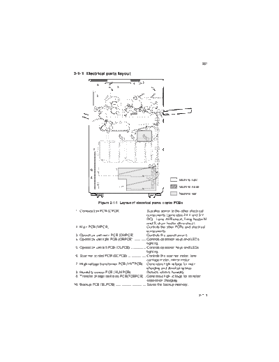
2-1-1 Electrical parts layout
5 4
3
6
9
7
2
10 1
8
Machine front
Machine inside
Machine rear
Figure 2-1-1 Layout of electrical parts: copier PCBs
1. Composition PCB (CPCB) ........................... Supplies power to the other electrical
components (generates 24 V and 5 V
DC). Lamp AVR circuit, fixing heater M
and S, drum heater drive circuit.
2. Main PCB (MPCB) ....................................... Controls the other PCBs and electrical
components.
3. Operation unit main PCB (OMPCB) ............ Controls the operation unit.
4. Operation unit right PCB (ORPCB) ............. Controls operation keys and LEDs
lighting.
5. Operation unit left PCB (OLPCB) ................ Controls operation keys and LEDs
lighting.
6. Scanner control PCB (SCPCB) ................... Controls the scanner motor, lens
carriage motor, mirror motor.
7. High voltage transformer PCB (HVTPCB) ... Generates high voltage for main
charging and developing bias.
8. Humidity sensor PCB (HUMPCB) ............... Detects relative humidity.
9. Transfer charger belt bias PCB(TCBPCB) .. Generates high voltage for transfer/
separation charging.
10. Backup PCB (BUPCB) ................................ Saves the backup memory.
2-1-1
367
7
2 8
1 9
3
4
10
31 16
15 14 17
12 13
18
5
11
19
20
6
23, 24 21
27 29
22
25, 26 Machine front
30
28 Machine inside
Machine rear
Figure 2-1-2 Layout of electrical parts: copier switches and sensors
1. Main switch (MSW) ...................................... Turns the AC power on and off.
2. Heater switch (HSW) ................................... Turns the transfer charger heater and
cassette heater on/off.
3. Front cover safety switch (FCSSW) ............ Breaks the safety circuit when the front
cover is opened or closed, and resets
paper misfeed detection.
4. Eject cover safety switch (ECSSW) ............. Breaks the safety circuit when the eject
cover is opened or closed, and resets
paper misfeed detection.
5. Paper feed cover safety switch 1 ................. Breaks the safety circuit when the
(PFCSSW1) upper right cover is opened or closed,
and resets paper misfeed detection.
6. Paper feed cover safety switch 2 ................. Breaks the safety circuit when the lower
(PFCSSW2) right cover is opened or closed, and
resets paper misfeed detection.
7. Scanner home position switch (SHPSW) .... Detects the optical system in the home
position.
8. Mirror home position switch (MHPSW) ........ Detects mirrors 4 and 5 in the home
positions.
2-1-2
367
9. Lens carriage home position switch ....... Detects the lens in the home position.
(LCHPSW)
10. Eject switch (ESW) ................................. Detects a paper misfeed in the fixing
section.
11. Waste toner detection switch .................. Detects the replacing time of the waste
(WTDSW) toner tank.
12. Transfer charger belt detection switch .... Detects the position of the transfer
(TCBDSW) charger belt.
13. Registration switch (RSW) ...................... Controls the secondary paper feed stop
timing.
14. Bypass paper switch (BYPPSW) ............ Detects the presence of paper on the
bypass tray.
15. Feed switch (FSW) ................................. Controls the secondary paper feed start
timing.
16. Bypass paper length switch .................... Detects the length of paper on the
(BYPPLSW) bypass tray.
17. Bypass paper width switch ..................... Detects the width of paper on the
(BYPPWSW) bypass tray.
18. Paper feed switch 1 (PFSW1) ................ Detects a paper misfeed.
19. Paper feed switch 2 (PFSW2) ................ Controls the primary paper feed and
detects a paper misfeed.
20. Paper feed switch 3 (PFSW3) ................ Controls the feed clutch 3 and detects a
paper misfeed.
21. Paper feed switch 4 (PFSW4) ................ Controls the feed clutch 4 and detects a
paper misfeed.
22. Paper feed switch 5 (PFSW5) ................ Controls the feed clutch 5 and detects a
paper misfeed.
23. Upper paper switch (PSW-U) ................. Detects the presence of paper in the
upper cassette.
24. Upper lift limit switch (LICSW-U) ............ Detects the upper cassette lift reaching
the upper limit.
25. Lower paper switch (PSW-L) .................. Detects the presence of paper in the
lower cassette.
26. Lower lift limit switch (LICSW-L) ............. Detects the lower cassette lift reaching
the upper limit.
*1 27. Upper paper length switch (PLSW-U) .... Detects the length of paper in the upper
cassette.
*2 27. Upper cassette detection switch ............. Detects the presence of the upper
(CDSW-U) cassette.
*1 28. Lower paper length switch (PLSW-L) ..... Detects the length of paper in the lower
cassette.
*2 28. Lower cassette detection switch ............. Detects the presence of the lower
(CDSW-L) cassette.
*1: For inch models only.
*2: For metric models only.
2-1-3
367
*1 29. Upper paper width switch (PWSW-U) .... Detects the width of paper in the upper
cassette.
*1 30. Lower paper width switch (PWSW-L) ..... Detects the width of paper in the lower
cassette.
31. Toner level detection sensor (TLDS) ...... Detects the toner level in the toner
hopper.
*1: For inch models only.
2-1-4
367
9
2 3
8
11
7
10 5 14
1
12 13
15
4
6
16
Machine front
17
Machine inside
Machine rear
Figure 2-1-3 Layout of electrical parts: copier motors
1. Scanner motor (SM) .................................... Drives the optical system.
2. Mirror motor (MM) ........................................ Drives mirrors 4 and 5.
3. Lens carriage motor (LCM) .......................... Drives the lens.
4. Drive motor (DM) ......................................... Drives the machine.
5. Image forming motor (IFM) .......................... Drives the image forming section.
6. Paper feed motor (PFM) .............................. Drives the paper feed and conveying
system.
7. Main charger fan motor (MCFM) ................. Ventilates the main charger section.
8. Optical section fan motor (OPFM) ............... Cools the optical section.
9. Cooling fan motor 2 (CFM2) ........................ Cools the machine inside.
10. Cooling fan motor 1 (CFM1) ........................ Cools the machine inside.
11. Developing unit fan motor (DFM) ................ Cools the developing section.
12. Fixing unit fan motor (FFM) ......................... Cools the ejection section.
13. Main charger cleaning motor (MCCM) ........ Cleans the main charger wire.
14. Toner feed motor (TFM) .............................. Replenishes toner.
15. Toner agitation motor (TAM) ....................... Agitates toner.
16. Upper paper cassette lift motor (PCLM-U) .. Drives the upper cassette lift.
17. Lower paper cassette lift motor (PCLM-L) ... Drives the lower cassette lift.
2-1-5
367
4
3 2
5
1
12
6
7
8
10
9
11
Machine front
Machine inside
Machine rear
Figure 2-1-4 Layout of electrical parts: copier clutches and solenoids
1. Transfer charger belt release clutch ............ Controls the position of the transfer
(TCBRCL) charger belt.
2. Bypass paper feed clutch (BYPCL) ............. Primary paper feed from the bypass
tray.
3. Registration clutch (RCL) ............................ Secondary paper feed.
4. Feed clutch 1 (FCL1) ................................... Controls the drive of the feed roller
(high speed).
5. Feed clutch 2 (FCL2) ................................... Controls the drive of the feed roller (low
speed).
6. Feed clutch 3 (FCL3) ................................... Controls the drive of the left feed roller
and vertical conveying roller A (upper).
7. Feed clutch 4 (FCL4) ................................... Controls the drive of the vertical
conveying roller A (lower).
8. Feed clutch 5 (FCL5) ................................... Controls the drive of the vertical
conveying roller B.
9. Feed clutch 6 (FCL6) ................................... Controls the drive of the vertical
conveying roller C.
10. Upper paper feed clutch (PFCL-U) .............. Primary paper feed from the upper
cassette.
2-1-6
367
11. Lower paper feed clutch (PFCL-L) .............. Primary paper feed from the lower
cassette.
12. Bypass solenoid (BYPSOL) ......................... Operates the bypass lift guide plate.
2-1-7
367
367-1
12
3
10
13
6 18 16
15 4, 5 11
7
17 1, 2
14
20 8
9
Machine front
19
Machine inside
Machine rear
Figure 2-1-5 Layout of electrical parts: copier other electrical parts
1. Toner sensor (TNS) ..................................... Detects the toner density in the
developing unit.
2. Developing thermistor (DEVTH) .................. Detects the developing unit
temperature.
3. Optical section thermostat (TH3) ................. Prevents overheating in the optical
system.
4. Fixing unit thermostat 1 (TH1) ..................... Prevents overheating in the fixing
section.
5. Fixing unit thermostat 2 (TH2) ..................... Prevents overheating in the fixing
section.
6. Fixing unit thermistor (FTH) ......................... Detects the heat roller temperature.
7. Drum thermistor (DRMTH) ........................... Detects the drum heater temperature.
8. Sorter relay (SRY) ....................................... Turns the AC power supplies of the
sorter on and off.
9. Power relay (PRY) ....................................... Turns the AC and 24 V DC power
supplies on and off.
10. Total counter (TC) ....................................... Displays the total number of copies
produced.
2-1-8
367-1
367
11. Blank lamps (BL) ......................................... Remove charge from non-image
forming areas of the drum surface.
12. Halogen lamp (HL) ...................................... Performs paper exposure.
13. Transfer charger heater (TCH) .................... Dehumidifies the transfer charger
section.
14. Fixing heater M (FHM) ................................. Heats the heat roller.
15. Fixing heater S (FHS) .................................. Heats the heat roller.
16. Drum surface potential sensor ..................... Detects the potential on the drum
(DSPSENS) surface.
17. Drum heater (DH) ........................................ Prevents drum condensation.
18. Cleaning lamp (CL) ...................................... Removes residual charge from the
drum surface.
19. Cassette heater 1 (CH1) .............................. Dehumidifies paper.
20. Cassette heater 2 (CH2) .............................. Dehumidifies paper.
2-1-9
367
1 9 7 8 6
10 2
5 4 3
12 11
Machine front Machine inside Machine rear
Figure 2-1-6 Layout of electrical parts: large paper deck PCB, switches and
sensors
1. Large paper deck interface PCB ................. Interfaces between the main PCB and
(LPDIFPCB) the other electrical components of the
large paper deck .
2. Large paper deck paper pass sensor 1 ....... Detects a paper misfeed and the
(LPDPPSENS1) presence of paper on the lift.
3. Large paper deck paper pass sensor 2 ....... Detects a paper misfeed and the
(LPDPPSENS2) presence of paper on the lift.
4. Large paper deck paper pass sensor 3 ....... Detects a paper misfeed and the
(LPDPPSENS3) presence of paper on the lift.
5. Large paper deck paper empty sensor ........ Detects the presence of paper in the
(LPDPESENS) left large paper deck.
6. Large paper deck level switch 1 .................. Detects the right large paper deck lift in
(LPDLSW1) the home position.
7. Large paper deck level switch 2 .................. Detects the left large paper deck lift in
(LPDLSW2) the home position.
8. Large paper deck upper switch 1 ................ Not used this copier.
(LPDUPSW1)
9. Large paper deck upper switch 2 ................ Not used this copier.
(LPDUPSW2)
10. Large paper deck open safety switch .......... Detects when the large paper deck is
(LPDOSSW) opened or closed.
11. Large paper deck level detection sensor 1 .. Detects the paper level in the right large
(LPDPLDSENS1) paper deck.
12. Large paper deck level detection sensor 2 .. Detects the paper level in the left large
(LPDPLDSENS2) paper deck.
2-1-10
367
4 5 3
1 2
Machine front Machine inside Machine rear
Figure 2-1-7 Layout of electrical parts: large paper deck motor and clutches
1. Large paper deck left lift motor .................... Drives the large paper deck left lift.
(LPDLM-L)
2. Large paper deck right lift motor .................. Drives the large paper deck right lift.
(LPDLM-R)
3. Large paper deck paper feed clutch 1 ......... Controls the drive of the large paper
(LPDPFCL1) deck paper feed roller 1, and the upper
and lower separation rollers.
4. Large paper deck paper feed clutch 2 ......... Controls the drive of the large paper
(LPDPFCL2) deck paper feed roller 2.
5. Large paper deck conveying clutch ............. Controls the drive of the large paper
(LPDCCL) deck paper conveying roller.
2-1-11
367
367-1
11
1 9 2 7
6 15
10 14
8 3
13 12
5 4
Machine front Machine inside Machine rear
Figure 2-1-8 Layout of electrical parts: feedshift and duplex sections
1. Feedshift switch (FSSW) ............................. Detects a paper misfeed in the feedshift
section.
2. Duplex paper switch (DUPPSW) ................. Detects a paper misfeed in duplex
entrance.
3. Duplex paper conveying switch ................... Detects a paper misfeed in the duplex
(DUPPCSW) paper conveying section.
4. Duplex eject switch (DUPESW) ................... Controls the duplex paper conveying
clutch.
5. Duplex registration switch (DUPRSW) ........ Detects a paper misfeed in the duplex
section.
6. Stock switch (STKSW) ................................ Detects the presence of paper in the
duplex unit.
7. Side registration home position switch ........ Detects the side registration guides in
(SRHPSW) the home positions.
8. Duplex registration clutch (DUPRCL) .......... Controls the drive of the duplex upper
registration roller.
9. Duplex paper conveying clutch .................... Controls the drive of the duplex upper
(DUPPCCL) paper conveying pulley and duplex
upper eject pulley.
10. Refeed clutch (RFCL) .................................. Controls the drive of the switchback
roller.
11. Feedshift solenoid (FSSOL) ........................ Operates the conveying shift guide.
12. Duplex forward solenoid (DUPFWDSOL) .... Operates the duplex forwarding pulley.
13. Duplex paper press solenoid ....................... Operates the duplex paper press plate.
(DUPPPSOL)
14. Duplex paper tapping solenoid .................... Operates the paper tapping guide.
(DUPPTSOL)
15. Side registration motor (SRM) ..................... Operates the side registration guides.
2-1-12
367
2
6 12
8
3 15
7 16 14 13
5
9 10 4 1 11
Machine front Machine inside Machine rear
Figure 2-1-9 Layout of electrical parts: RDH PCBs and switches
1. RDH main PCB (RDHMPCB) ...................... Communicates with the copier and
controls the RDH electrical
components.
2. LED PCB (LEDPCB) ................................... Consists of the LED display circuits.
3. Original reading PCB (ORPCB) ................... Detects the special paper for program
ahead mode.
4. RDH safety switch (RDHSSW) ................... Detects whether the RDH is opened or
closed.
5. Original reverse cover safety switch ............ Detects whether the original reverse
(ORCSSW) cover is opened or closed.
6. Original partition home position switch ........ Detects original partition in the home
(OPHPSW) positions.
7. Original set switch (OSSW) ......................... Detects the presence of original on the
original table.
8. Original registration switch (ORSW) ............ Controls the original paper feed and
reversing, and detects a original
misfeed.
9. Original feed switch (OFSW) ....................... Detects the passing timing of original
being fed or reversed and a original
misfeed.
10. Original preset switch (OPSSW) ................. Detects the presence of original on the
original table and rotating original feed
pulley.
11. Original eject switch (OESW) ...................... Detects the passing timing of original
being ejected and a original misfeed.
12. Original eject cover safety switch ................ Detects whether the original eject cover
(OECSSW) is opened or closed.
13. Original length switch 1 (OLSW1) ............... Detects the length(1) of original.
14. Original length switch 2 (OLSW2) ............... Detects the length(2) of original.
15. Original moving home position switch ......... Detects original moving plate in the
(OMHPSW) home positions.
16. Original width switch (OWSW) .................... Detects the width of original.
2-1-13
367
5 6 4
13
12 8 3 14
11 9
2 7 10
1
Machine front Machine inside Machine rear
Figure 2-1-10 Layout of electrical parts: RDH motors, solenoids and sensors
1. Original conveying motor (OCM) ................. Drives the original conveying section.
2. Original feed motor (OFM) ........................... Drives the original feed section.
3. Original moving motor (OMM) ..................... Drives the original moving and original
separation plates.
4. Original eject motor (OEM) .......................... Drives the original eject section.
5. Original feed solenoid (OFSOL) .................. Controls the original press plate.
6. Original strike solenoid (OSTSOL) .............. Controls the original size indicator line
plate.
7. Original stopper solenoid (OSSOL) ............. Controls the original stopper.
8. Original partition lever solenoid ................... Controls the original partition lever.
(OPLSOL)
9. Original eject solenoid (OESOL) ................. Controls the direction of the original
ejection.
10. Original moving solenoid (OMSOL) ............. Controls the moving of the original
moving plate.
11. Original partition solenoid (OPSOL) ............ Controls the moving of the original
partition plate.
12. Original feed motor pulse sensor ................. Generates original feed motor clock
(OFMPS) pulses.
13. Original conveying motor pulse sensor ....... Generates original conveying motor
(OCMPS) clock pulses.
14. Original eject motor pulse sensor ................ Generates original eject motor clock
(OEMPS) pulses.
2-1-14
◦ Jabse Service Manual Search 2026 ◦ Jabse Pravopis ◦ onTap.bg ◦ Other service manual resources online : Fixya ◦ eServiceinfo