Service Manuals, User Guides, Schematic Diagrams or docs for : Keithley Appnotes LowCurtMsmntsAppNote
<< Back | HomeMost service manuals and schematics are PDF files, so You will need Adobre Acrobat Reader to view : Acrobat Download Some of the files are DjVu format. Readers and resources available here : DjVu Resources
For the compressed files, most common are zip and rar. Please, extract files with Your favorite compression software ( WinZip, WinRAR ... ) before viewing. If a document has multiple parts, You should download all, before extracting.
Good luck. Repair on Your own risk. Make sure You know what You are doing.
Image preview - the first page of the document
>> Download LowCurtMsmntsAppNote documenatation <<
Text preview - extract from the document
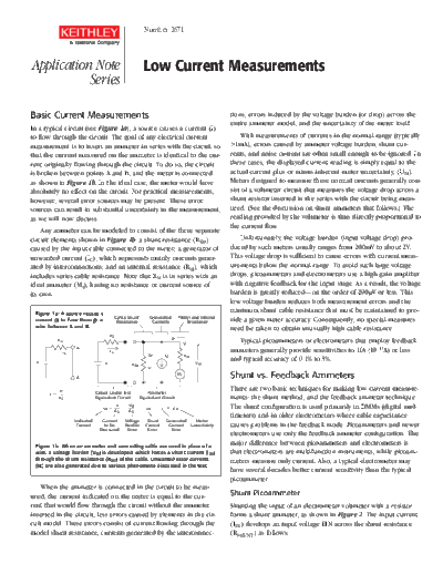
                                                            Number 1671


Application Note                                           Low Current Measurements
           Series

Basic Current Measurements                                                                              tions, errors induced by the voltage burden (or drop) across the
                                                                                                        entire ammeter model, and the uncertainty of the meter itself.
In a typical circuit (see Figure 1a), a source causes a current (I)
to flow through the circuit. The goal of any electrical current                                             With measurements of currents in the normal range (typically
measurement is to insert an ammeter in series with the circuit so                                       >1mA), errors caused by ammeter voltage burden, shunt cur
that the current measured on the ammeter is identical to the cur                                        rents, and noise current are often small enough to be ignored. In
rent originally flowing through the circuit. To do so, the circuit                                      these cases, the displayed current reading is simply equal to the
is broken between points A and B, and the meter is connected                                            actual current plus or minus inherent meter uncertainty, (UM).
as shown in Figure 1b. In the ideal case, the meter would have                                          Meters designed to measure these normal currents generally con
absolutely no effect on the circuit. For practical measurements,                                        sist of a voltmeter circuit that measures the voltage drop across a
however, several error sources may be present. These error                                              shunt resistor inserted in the series with the circuit being meas
sources can result in substantial uncertainty in the measurement,                                       ured. (See the discussion on shunt ammeters that follows.) The
as we will now discuss.                                                                                 reading provided by the voltmeter is thus directly proportional to
                                                                                                        the current flow.
    Any ammeter can be modeled to consist of the three separate
circuit elements shown in Figure 1b: a shunt resistance (RSH)                                              Unfortunately, the voltage burden (input voltage drop) pro
caused by the input cable connected to the meter; a generator of                                        duced by such meters usually ranges from 200mV to about 2V.
unwanted current (IC), which represents mainly currents gener                                           This voltage drop is sufficient to cause errors with current meas
ated by interconnections; and an internal resistance (R M), which                                       urements below the normal range. To avoid such large voltage
includes series cable resistance. Note that R M is in series with an                                    drops, picoammeters and electrometers use a high gain amplifier
ideal ammeter (MI), having no resistance or current source of                                           with negative feedback for the input stage. As a result, the voltage
its own.                                                                                                burden is greatly reduced--on the order of 200
◦ Jabse Service Manual Search 2026 ◦ Jabse Pravopis ◦ onTap.bg ◦ Other service manual resources online : Fixya ◦ eServiceinfo