Service Manuals, User Guides, Schematic Diagrams or docs for : Keithley Appnotes 2521 Mil Switching
<< Back | HomeMost service manuals and schematics are PDF files, so You will need Adobre Acrobat Reader to view : Acrobat Download Some of the files are DjVu format. Readers and resources available here : DjVu Resources
For the compressed files, most common are zip and rar. Please, extract files with Your favorite compression software ( WinZip, WinRAR ... ) before viewing. If a document has multiple parts, You should download all, before extracting.
Good luck. Repair on Your own risk. Make sure You know what You are doing.
Image preview - the first page of the document

>> Download 2521 Mil Switching documenatation <<
Text preview - extract from the document
                                     A   G R E AT E R   M E A S U R E   O F   C O N F I D E N C E        (a)


Switch Systems                                                                 (b)


for Aerospace
and Defense
Testing
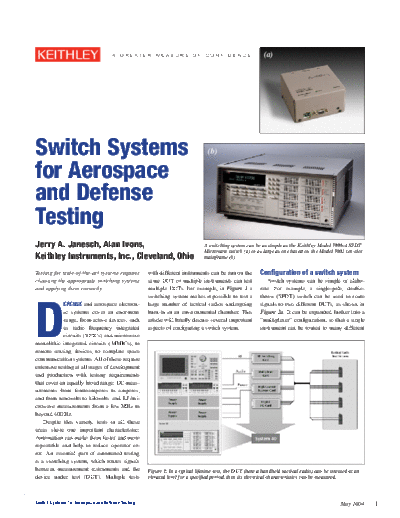
Jerry A. Janesch, Alan Ivons,                                                 A switching system can be as simple as the Keithley Model 7999-4 SPDT
                                                                              Microwave switch (a) or as large as one based on the Model 7002 ten-slot
Keithley Instruments, Inc., Cleveland, Ohio                                   mainframe (b).


Testing for state-of-the-art systems requires      with different instruments can be run on the         Configuration of a switch system
choosing the appropriate switching systems         same DUT or multiple instruments can test                Switch systems can be simple or elabo-
and applying them correctly.                       multiple DUTs. For example, in Figure 1 a            rate. For example, a single-pole, double-


D
                                                   switching system makes it possible to test a         throw (SPDT) switch can be used to route
            EFENSE and aerospace electron-         large number of tactical radios undergoing           signals to two different DUTs, as shown in
            ic systems cover an enormous           burn-in in an environmental chamber. This            Figure 2a. It can be expanded further into a
            range, from active devices, such       article will briefly discuss several important       "multiplexer" configuration, so that a single
            as radio frequency integrated          aspects of configuring a switch system.              instrument can be routed to many different
            circuits (RFICs) and microwave
monolithic integrated circuits (MMICs), to
remote sensing devices, to complete space
communication systems. All of these require
extensive testing at all stages of development
and production with testing requirements
that cover an equally broad range: DC meas-
urements from femtoamperes to amperes,
and from nanovolts to kilovolts, and RF/mi-
crowave measurements from a few MHz to
beyond 40GHz.
    Despite this variety, tests in all these
areas share one important characteristic:
Automation can make them faster and more
repeatable and help to reduce operator er-
ror. An essential part of automated testing
is a switching system, which routes signals
between measurement instruments and the            Figure 1: In a typical lifetime test, the DUT (here a handheld tactical radio) can be stressed at an
device under test (DUT). Multiple tests            elevated level for a specified period, then its electrical characteristics can be measured.


Switch Systems for Aerospace and Defense Testing                                                                                              May 2004    1
                                                                                                             Electrical specifications for RF and
                                                                                                             microwave switching systems
                                                                                                                 Bandwidth--Most switch system users
                                                                                                             would like to have as wide and as flat a band-
                                                                                                             width switch as possible. However, if the
                                                                                                             equipment to be tested involves no frequen-
                                                                                                             cies higher than 18GHz, it's a waste of mon-
                                                                                                             ey to use a 40GHz switch. It's also important
                                                                                                             to remember that as bandwidth increases, the
                                                                                                             selection of connectors and cables becomes
                                                                                                             more important.
                                                                                                                 Insertion Loss--Any component added
    Figure 2: (a) A single-pole, double-throw                                                                to the signal path will cause some degree of
                                                        Figure 4: A nonblocking matrix makes it pos-         loss. This loss is especially severe at higher
    (SPDT) switch can be used to route signals to
                                                        sible to switch any signal to any DUT at any
    two different DUTs. (b) This can be expanded                                                             or resonant frequencies. When signal level is
                                                        time. While this configuration has the highest
    into a "multiplexer" configuration, so that a
    single instrument can be routed to many differ-
                                                        flexibility, it's also the most expensive.           low or noise is high, insertion loss is particu-
    ent DUTs, as in this 1x16 multiplexer. Both of                                                           larly important.
    these use a "blocking" arrangement, in which        ing receiving ranges and multipath effects.              Voltage Standing Wave Ratio (VSWR)--
    only one signal path is active at any given time.
                                                        This means adding both active components,            Any mismatched impedances in the signal
                                                        like amplifiers, and passive components, like        path (Figure 6) will increase VSWR. For op-
    DUTs. Figure 2b shows a 1
◦ Jabse Service Manual Search 2024 ◦ Jabse Pravopis ◦ onTap.bg ◦ Other service manual resources online : Fixya ◦ eServiceinfo