Service Manuals, User Guides, Schematic Diagrams or docs for : Keithley Appnotes 2991_RFXsistor_Pulse_Test

<< Back | Home

Most service manuals and schematics are PDF files, so You will need Adobre Acrobat Reader to view : Acrobat Download Some of the files are DjVu format. Readers and resources available here : DjVu Resources
For the compressed files, most common are zip and rar. Please, extract files with Your favorite compression software ( WinZip, WinRAR ... ) before viewing. If a document has multiple parts, You should download all, before extracting.
Good luck. Repair on Your own risk. Make sure You know what You are doing.


Image preview - the first page of the document
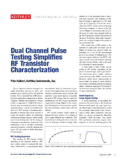
2991_RFXsistor_Pulse_Test


>> Download 2991_RFXsistor_Pulse_Test documenatation <<

Text preview - extract from the document
                                       A   GREAT ER          M EA SU R E          O F    C O N F I D E N C E   referred to as the operating point or quies-
                                                                                                               cent point (q-point). The technique in this
                                                                                                               type of testing is application of a low duty
                                                                                                               cycle pulse (typically <1%) to the device
                                                                                                               under test (DUT), which avoids self-heating
                                                                                                               and carrier trapping. As shown in the left
                                                                                                               view of Figure 1, each point on the curve is
                                                                                                               the result of a pulse measurement made on
                                                                                                               the DUT during the settled or flat portion of
                                                                                                               the pulse. In practice, many pulse measure-
                                                                                                               ments are averaged to improve the quality of
                                                                                                               measurement results.
                                                                                                                   The second type of PIV testing is the


Dual Channel Pulse
                                                                                                               transient or single pulse test (right view in
                                                                                                               Figure 1). In this case, the test results are
                                                                                                               presented as a view of the measurement


Testing Simplifies
                                                                                                               pulse, or an average of multiple pulses. The
                                                                                                               measured signal is plotted as the DUT's volt-
                                                                                                               age or current versus time response, showing


RF Transistor                                                                                                  any time-varying changes, such as the onset
                                                                                                               of self-heating or charge trapping.


Characterization
                                                                                                                   A wide range of pulse widths can be
                                                                                                               useful in PIV testing, depending on the
                                                                                                               device or material type and test parameters.
                                                                                                               For millisecond pulse widths, ordinary
                                                                                                               source-measure units (SMUs) can be used.
                                                                                                               However, shorter pulses (microseconds to
Pete Hulbert, Keithley Instruments, Inc.                                                                       nanoseconds) are generally more effective
                                                                                                               for avoiding self-heating and charge trapping
                                                                                                               effects. Therefore, short-pulse PIV testing of
    Device engineers and test managers are               measurement. Since RF transistors are pri-            RF transistors generally allows the creation
under tremendous pressure to make sure                   marily used in applications where non-linear          of more useful models.
products get to market quickly and perform               responses are the norm, such as switches and
reliably. This is especially true of RF transis-         amplifiers, large signal analysis is typically        Small Signal vs.
tors destined for hot communications market              the goal of PIV testing. The two main test            Large Signal Testing
segments. Whether the technology is based                methodologies are PIV sweeps and transient               A useful dichotomy in describing RF
on III-V compounds or LDMOS, RF transis-                 (single pulse) testing (Figure 1). By using a         transistor characterization is the distinction
tor tests must accurately characterize design            dual-channel pulse source-measure system,             between small signal and large signal test-
and performance 


◦ Jabse Service Manual Search 2024 ◦ Jabse PravopisonTap.bg ◦ Other service manual resources online : FixyaeServiceinfo