Service Manuals, User Guides, Schematic Diagrams or docs for : Keithley Appnotes 2w_4w_ohms
<< Back | HomeMost service manuals and schematics are PDF files, so You will need Adobre Acrobat Reader to view : Acrobat Download Some of the files are DjVu format. Readers and resources available here : DjVu Resources
For the compressed files, most common are zip and rar. Please, extract files with Your favorite compression software ( WinZip, WinRAR ... ) before viewing. If a document has multiple parts, You should download all, before extracting.
Good luck. Repair on Your own risk. Make sure You know what You are doing.
Image preview - the first page of the document
>> Download 2w_4w_ohms documenatation <<
Text preview - extract from the document
What is the difference between 4-wire and 2-wire Ohms measurements?
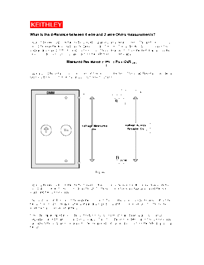
Figure 1 below illustrates the method used in 2-wire Ohms measurement. The test current (I) is
forced through the test lead into the Device Under Test (R). The Voltmeter (Vm) measures the
voltage developed at the HI and LO terminals. This voltage will be from the IxR drop across the
Device Under Test (DUT) as well as from the IxR from the test leads.
Measured Resistance = Vm = Rs + (2xRLead )
I
Typical Lead Resistance is in the range of 1mohm to 100mohms. This Lead Resistance will be a
significant source of error if your DUT is below 10 Ohms.
Test Current
DMM Hi
R Lead
Voltage Measured Voltage Acorss
Vm Resistor(Vr)
Vm
Lo R Lead
Figure 1
Figure 2 below illustrates the method used in 4-wire Ohms measurement. To use 4-wire ohms,
four distinct connections are made to the DUT; these connections are typically called the source
leads and the sense leads.
The Test current (I) is forced through the DUT as before on the source leads. However, this time
the Voltmeter (Vm) measures the voltage developed only at the connection point of the sense
leads that are connected at the DUT.
Since the input impedance of the voltmeter is many orders of magnitude larger than the DUT,
negligible current flows into the Sense leads. Therefore, there is no IxR drop in the sense leads
over which the voltage is measured. The measured voltage will be only from the IxR drop across
the DUT.
R Lead Test Current
DMM
Source Hi
R Sense Current
Sense Hi Lead
Vm R
R
Lead
Sense Lo
R
Source Lo Lead
Figure 2
◦ Jabse Service Manual Search 2026 ◦ Jabse Pravopis ◦ onTap.bg ◦ Other service manual resources online : Fixya ◦ eServiceinfo