Service Manuals, User Guides, Schematic Diagrams or docs for : Keithley Appnotes 2Wire_4Wire Resistance Article

<< Back | Home

Most service manuals and schematics are PDF files, so You will need Adobre Acrobat Reader to view : Acrobat Download Some of the files are DjVu format. Readers and resources available here : DjVu Resources
For the compressed files, most common are zip and rar. Please, extract files with Your favorite compression software ( WinZip, WinRAR ... ) before viewing. If a document has multiple parts, You should download all, before extracting.
Good luck. Repair on Your own risk. Make sure You know what You are doing.


Image preview - the first page of the document
2Wire_4Wire Resistance Article


>> Download 2Wire_4Wire Resistance Article documenatation <<

Text preview - extract from the document
                                                                                                         Two-Wire Resistance
                                                                                                         Measurements
                                                   A Greater Measure of Confidence
                                                                                                         Figure 2 represents a two-wire resistance test
                                                                                                         configuration employing the constant cur-
                                                                                                         rent method.
                                                                                                            The main measurement issue with the
                                                                                                         two-wire method, as applied to low resist-
                                                                                                         ance measurements, is that the total lead
                                                                                                         resistance (R LEAD) is added to the measure-
                                                                                                         ment. Because the test current (I) causes a
                                                                                                         small but significant voltage drop across the
                                                                                                         lead resistances, the voltage (VM) measured


two-Wire vs. Four-Wire
                                                                                                         by the meter won't be exactly the same as the
                                                                                                         voltage (VR) directly across the test resist-
                                                                                                         ance (R), and considerable error can result.


Resistance Measurements:
                                                                                                         Typical lead resistances range from 10m
                                                                                                         to 1, so it's very difficult to obtain accurate
                                                                                                         two-wire resistance measurements when


Which Configuration Makes                                                                                the resistance under test is lower than 100
                                                                                                         because the resistance of interest will be


sense for Your Application?
                                                                                                         completely swamped by the lead resistance.
                                                                                                         In fact, lead resistance will be the dominant
                                                                                                         source of error. For example, using test leads
                                                                                                         with a 100m combined resistance to per-
                                                                                                         form a two-wire resistance measurement
                                                                                                         on a 500m resistor will result in a 20%
Jerry Janesch                                                                                            measurement error in addition to that of the
Keithley Instruments, Inc.                                                                               instrument.


M
                 ost precision digital multi-      impedance, virtually all the test current             Four-Wire (Kelvin) Resistance
                 meters (DMMs) and many            (1mA) flows through the DUT.                          Measurements
                 Source Measurement Units                                                                Due to the limitations of the two-wire
                 (SMUs) offer both two-wire        Table 1. Typical DMM ranges and test currents         method, a different approach is used for low
                 and four-wire resistance             Measurement                                        resistance measurements that reduce the
measurement capabilities. However, these                 Range                    Test Current           effect of test lead resistance. For measuring
two techniques are not equally well suited              100                            1 mA              DUTs with resistances equal to or less than
for all resistance measurement applications.               1 k                         1 mA              1k, test engineers may use the four-wire
This article offers a quick overview of how to            10 k                      100 A                (Kelvin) connection shown in Figure 3.
determine the most appropriate technique                100 k                         10 A               Because the voltage is measured at the DUT,
for a specific application.                                1 M                         1 A               voltage drop in the test leads is eliminated
    DMMs typically employ the constant-                   10 M                       0.1 A               (this voltage could be significant when meas-
current method to measure resistance,                   100 M                        0.1 A               uring low-resistance devices).
which sources a constant current (ISOUR) to                                                                  With this configuration, the test current
the device under test (DUT) and measures           (Source Keithley Model 2110)                          (I) is forced through the test resistance (R)
the voltage (VMEAS). Resistance (R DUT) is
then calculated and displayed using the
known current and measured voltage (R DUT                                                                Input HI
= VMEAS/ISOUR). Figure 1 shows a simple dia-
gram of the constant-current test.
   The test current sourced to the DUT                                    VMEAS     V            ISOUR                       DUT
depends on the selected measurement range
(Table 1). For example, for the 100 range,
the test current is 1mA. Because the volt-
meter of a typical DMM has very high input

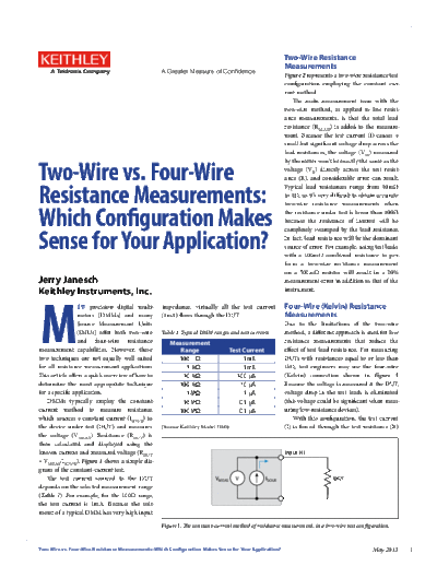
                                                   Figure 1. The constant-current method of resistance measurement, in a two-wire test configuration.


Two-Wire vs. Four-Wire Resistance Measurements: Which Configuration Makes Sense for Your Application?                                        May 2013      1
                                                                                                                 via one set of test leads, while the voltage
               DMM
                                                           RLEAD              Test Current (I)                   (VM) across the DUT is measured through a
                                         HI
                                                                                                                 second set of leads (sense leads).
                                                                                                                    Although some small current (typically
                                                                                                                 less than 100pA) may flow through the sense
                                                            Lead
                 I            VM                  VM     Resistances         VR          R        Resistance     leads, it is usually negligible and can gener-
                                                                                                  Under Test
                                                                                                                 ally be ignored for all practical purposes.
                                                           RLEAD                                                 Therefore the voltage measured by the meter
                                         LO
                                                                                                                 (VM) is essentially the same as the voltage
                                                                                                                 (VR) across the resistance (R). As a result, the
                                                  VM = Voltage measured by meter
                                                                                                                 resistance value can be determined much
                                                  VR = Voltage across resistor
                                                                                                                 more accurately than with the two-wire
                                                                                  VM
                                                  Measured Resistance =                  = R + (2 


◦ Jabse Service Manual Search 2024 ◦ Jabse PravopisonTap.bg ◦ Other service manual resources online : FixyaeServiceinfo