Service Manuals, User Guides, Schematic Diagrams or docs for : Keithley KPCI KPCI-3130_AN
<< Back | HomeMost service manuals and schematics are PDF files, so You will need Adobre Acrobat Reader to view : Acrobat Download Some of the files are DjVu format. Readers and resources available here : DjVu Resources
For the compressed files, most common are zip and rar. Please, extract files with Your favorite compression software ( WinZip, WinRAR ... ) before viewing. If a document has multiple parts, You should download all, before extracting.
Good luck. Repair on Your own risk. Make sure You know what You are doing.
Image preview - the first page of the document

>> Download KPCI-3130_AN documenatation <<
Text preview - extract from the document
                                           Number 2266


Application Note                           System Tests With the KPCI-3130 Series
          Series                           Analog Output Card

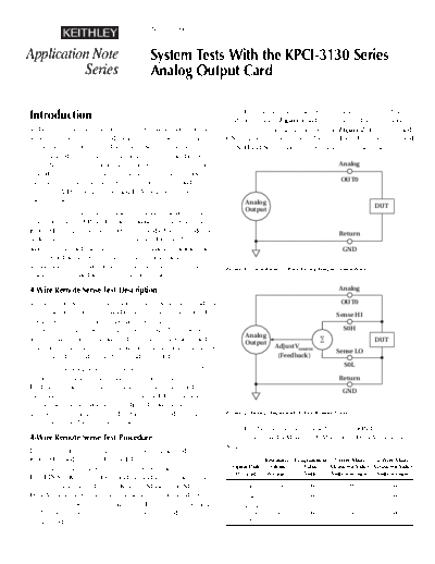
                                                                             The load will be connected to the analog output in 2-wire
Introduction                                                           mode as shown in Figure 1 and then connected in 4-wire mode
Today, the electronics community is experiencing a migration           using the sense line inputs as shown in Figure 2. The OUT0 and
away from traditional test and measurement philosophies and            GND signals will be connected to pins 1 and 19 respectively, and
encompassing a more hybrid approach. Several years ago, if one         the S0H and S0L signals will be connected to pins 2 and 20.
were required to generate or to measure very precise data points,
few solutions were available other than benchtop instrumenta-                                                      Analog
tion. However, the continued evolution of electronic components
has lead to the fabrication of precise voltage sources and high-                                                    OUT0
resolution A/D (analog/digital) and D/A hardware, creating a
variety of new solutions.                                                      Analog
                                                                               Output                                            DUT
      The ability to generate instrument quality analog voltages
is available in the KPCI-3130 Series analog output boards. The
KPCI-3130 is designed to the PCI-bus standard and provides a                                                       Return
wide feature set that is typically not seen in PC-based plug-in
analog output hardware. Two of the most unique characteristics                                                      GND
of the board are the 4-wire remote sense feature and the
4-quadrant source/sink operation. The functionality of these           Figure 1. Conventional 2-Wire Analog Output Connections
features is illustrated in the following test examples.

4-Wire Remote Sense Test Description                                                                               Analog

The ability to perform 4-wire remote sense operations provides a                                                    OUT0
significant advantage over standard analog output hardware. This                                                  Sense HI
feature becomes of critical importance when generating control
signals over long distances. Significant voltage drops can occur                                                     S0H
                                                                               Analog
as the result of cable resistances, device interconnections, and                                                                 DUT
                                                                               Output
terminations; therefore, the programmed output value may not be                              Adjust Vsource
                                                                                                                  Sense LO
the voltage delivered to the device under test (DUT).                                         (Feedback)
                                                                                                                     S0L
       Incorporating 4-wire remote sense functionality provides
the ability to connect sense leads directly to the input of the                                                    Return
DUT. The sense high and low connections allow the card to mea-
                                                                                                                    GND
sure (sense) the actual voltage present at the DUT. The analog
output can then be automatically adjusted, transparently to the
user, to ensure that the required voltage is supplied, regardless of   Figure 2. Analog Output with 4-Wire Remote Sense
cable lengths and interconnection losses.
                                                                             The data below was obtained using the KPCI-3130's
4-Wire Remote Sense Test Procedure                                     source feature and a Model 2700 Multimeter/Data Acquisition
                                                                       System:
In this test, a known voltage level will be programmed from the
KPCI-3130 and connected to the DUT using several different                              Resistance Programmed 2-Wire Mode        4-Wire Mode
cable lengths. The output voltage will be programmed with                Signal Path     (Ohms         Value  Measured Value Measured Value
                                                                          (Per lead)    Per lead)     (Volts) (Volts w/o sense) (Volts w/sense)
ExceLINXTM (Keithley's Excel add-in), and the resistance of the
cable will be measured using a Keithley Model 2700 Multimeter/            10 ft cable      0.5266      8.000         7.999           8.000
Data Acquisition System that is set to 4-wire ohms mode. For             100 ft cable       2.5        8.000         7.920           8.000
comparison purposes, the voltage at the DUT will also be meas-             6 relays, 4
ured without remote sense (this is typically referred to as            interconnections,    4.06       8.000         7.360           8.000
2-wire mode).                                                              20 ft cable
      The data clearly indicates that cabling and device intercon-            The analog output voltage will now be a function of the
nections can be significant sources of error.                           voltage programmed, and sensed, across the shunt resistor. The
                                                                        acceptable shunt voltage levels can once again be determined
                                                                        using Ohm's Law and the specified current:
Constant Current Source                                                         Vmaxshunt = 20mA
◦ Jabse Service Manual Search 2024 ◦ Jabse Pravopis ◦ onTap.bg ◦ Other service manual resources online : Fixya ◦ eServiceinfo