Service Manuals, User Guides, Schematic Diagrams or docs for : Keithley KPCI KPCI3100_ATrig_Pin
<< Back | HomeMost service manuals and schematics are PDF files, so You will need Adobre Acrobat Reader to view : Acrobat Download Some of the files are DjVu format. Readers and resources available here : DjVu Resources
For the compressed files, most common are zip and rar. Please, extract files with Your favorite compression software ( WinZip, WinRAR ... ) before viewing. If a document has multiple parts, You should download all, before extracting.
Good luck. Repair on Your own risk. Make sure You know what You are doing.
Image preview - the first page of the document

>> Download KPCI3100_ATrig_Pin documenatation <<
Text preview - extract from the document
     Accessing the Analog Trigger of KPCI-3110 or KPCI-3116

The DriverLINX code below is typical VB or C/C++ for specification of an analog
triggering source. In this case, the analog trigger is used as a stop event, but it
could used to specify the start event instead by use of the corresponding
properties or members of the Service Request.

SR.Evt_Stp_aiChannel = 0
SR.Evt_Stp_aiGainCode = SR.DLGain2Code(-1)

m_pSR->stop.u.aiEvent.channel = 0;
m_pSR->stop.u.aiEvent.gain = Gain2Code(0,AI,-1);


In this case, the board's analog channel 0 will be used as the triggering source.
This analog input channel has gains of 1, 2, 4 or 8.

The property of the DriverLINX driver for the gain to apply to the triggering source
is defined as 16bits wide. However, it need not be that wide as plug-in boards do
not typically have sufficient range options to require it.

The vast of majority of plug-in boards have only 8 possible range selections,
comprised of the 4 available gains and the unipolar or bipolar selection.
However, there are exceptions such as the KPCI-3108, which as has 12 gains.
These 12 gains combined with the unipolar or bipolar selection results in 24
possible ranges. These 24 ranges would only require 5 bits to uniquely store
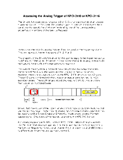
their values as illustrated below.


DriverLINX makes use of the upper, unused bits for special purpose features that
your board may have. In the case of analog input channels, these upper bits can
be used to control Single Ended or Differential mode and to access the high
speed digital I/O features of the boards covered by the KPCI3100 driver.

For analog triggering with KPCI-3116 or KPCI-3110, indicate that you want to
use the dedicated analog trigger input as the triggering source by programming
the Service Request to make use of channel 0 but at a gain value of 8000 (hex)
to differentiate it from the analog input channel 0.
SR.Evt_Stp_aiChannel = 0
SR.Evt_Stp_aiGainCode = &H8000

m_pSR->stop.u.aiEvent.channel = 0;
m_pSR->stop.u.aiEvent.gain = 0x8000;
◦ Jabse Service Manual Search 2024 ◦ Jabse Pravopis ◦ onTap.bg ◦ Other service manual resources online : Fixya ◦ eServiceinfo