Service Manuals, User Guides, Schematic Diagrams or docs for : Keithley 103A 103A(Model103ANanavolt_AMP)

<< Back | Home

Most service manuals and schematics are PDF files, so You will need Adobre Acrobat Reader to view : Acrobat Download Some of the files are DjVu format. Readers and resources available here : DjVu Resources
For the compressed files, most common are zip and rar. Please, extract files with Your favorite compression software ( WinZip, WinRAR ... ) before viewing. If a document has multiple parts, You should download all, before extracting.
Good luck. Repair on Your own risk. Make sure You know what You are doing.


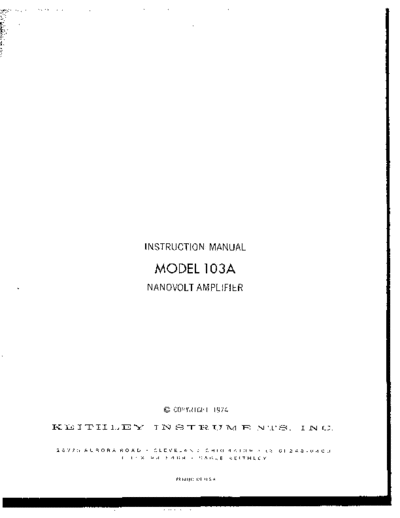
Image preview - the first page of the document
103A(Model103ANanavolt_AMP)


>> Download 103A(Model103ANanavolt_AMP) documenatation <<

Text preview - extract from the document
                             INSTRUCTION           MANUAL


                                MODEL 103A
                             NANOVOLT         AMPLIFIER


                                   0   COPYRIGHT    1974

KEITHLEY                       INSTRUMENTS.                                      I   NC.


 20775     AURORA   ROAD       CLEVELAND.        OHIO      R413Y      ,216,   24~~0400
                    TELEX~    98~5469          CAOLE       KEITHLEY


                                        PRlNTED ".SA.
                                              IN
CONTENTS
                                   ILLUSTRATIONS


Fig.        NO.                                  Ti,tle                                 ,`URC

        1         Front    Panel, wadcl,     103*.                                        1
        2         Front    Panel Controls      and Terininal~s.                           3
        3         Rear    Panel - Models      103A and 1031*.                             3
        4         overall      Block ILt@-am.                                             4
        5         Single-Ended        Mode.                                               4
        6         Uifferenrinl        Mode.                                               4
        7a        Power Rcceptncle.
        7b        Power Ilqmfi connection.                                                5
        8         Johnson Noise/ Hz Versus Source Resistance.                             5
        9         cain/Phnse       vs. Frequency for R-C Type Filter.                     6
       10         Equivalent       circuit   Far Noise Analysis.                          9
       11         use Of Model 1037 Transformer.                                         10
       12         Noise Bandwidth.                                                       10
       13a        Noise CoDtoUr Single-Ended            Mode.                            11
       13b        Noise Contour Oiiferential            Mode.                            11
       14         use as an cmill.oscope            Preamplifier.                        12
       15         "se in System 84 Lockin Amplifier.                                     12
       16         Model 2000 Rack Mounring.                                              13
       17         Model 100, Dual Kack Mounting.                                         14
       18         Overall      Block r1i.ap,ram.                                         16
       19         Non-inverting         Stage "A".                                       16
       20         Non-inverting         stage '93".                                      16
       21         Single-ended        Mode.                                              17
       22         "ifferenfisl        Mode.                                              17
       23         Nan-inverting         stage "I?".                                      17
       24         Nan-inverting      Stage    "F".                                       17
       25         High-Law cut Filter.                                                   18
       26         DC Offset Adjustment.                                                  18
       27         t18" Power supply.                                                     19
       28         camponent Layout,    K-293.                                            19
       29         component Layout,    PC-294             (Mother Board).                20
       30         Component Layout,    PC-295             (Model 1031A Power Supply).    21
       31         Component l.uyout,   PC-261             (Model 1031A Regulator).       22
       32         Tese Set-q   For Frequency               Response Check.               24
       33         Chassis Assembly,    Exploded             View.                        29
       34         Bottom cover Assembly.                                                 29
                                                                        SPECIFICATIONS


                         SPECIFICATIONS


       I           300      "          var         72982    538-037          C175-7/25P   29
c212    .0022        Ifi           1000     v          CcrD        72982    81100OXSF0222K   C22-.0022H   29
C213    .0022        Iii`          1000     v          CerD        72982    811000X5F02%2K   C22-.0022M   29
C214    100          $lF           15".     10%        I:TT        06751    TS"SI5107h       C205-lOON    29
C215    100          @F            I"",     10%        ETT         06751    TSD515107A       C205-100&f   29


0874                                                                                                              31
                       CEA-1%-l%      ma-15K      29
                       CEA-15K-1%     R88-15K     29
                       CEA-LOOK-1%    K88-1"OK    29
                       WA-lOOK-1%     R88-10


◦ Jabse Service Manual Search 2024 ◦ Jabse PravopisonTap.bg ◦ Other service manual resources online : FixyaeServiceinfo