Service Manuals, User Guides, Schematic Diagrams or docs for : Keithley 2600 _PA-916 (A - Jun 2005)(Model 2600)
<< Back | HomeMost service manuals and schematics are PDF files, so You will need Adobre Acrobat Reader to view : Acrobat Download Some of the files are DjVu format. Readers and resources available here : DjVu Resources
For the compressed files, most common are zip and rar. Please, extract files with Your favorite compression software ( WinZip, WinRAR ... ) before viewing. If a document has multiple parts, You should download all, before extracting.
Good luck. Repair on Your own risk. Make sure You know what You are doing.
Image preview - the first page of the document
>> Download _PA-916 (A - Jun 2005)(Model 2600) documenatation <<
Text preview - extract from the document
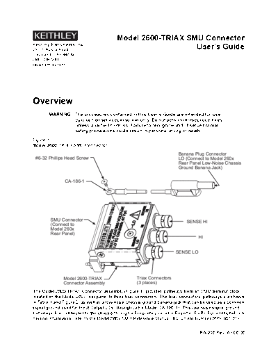
                                         Model 2600-TRIAX SMU Connector
Keithley Instruments, Inc.
28775 Aurora Road                                           User's Guide
Cleveland, Ohio 44139
(440) 248-0400
www.keithley.com


Overview
        WARNING The procedures contained in this User's Guide are intended for use
                by qualified service personnel only. Do not perform these procedures
                unless qualified to do so. Failure to recognize and observe normal
                safety precautions could result in personal injury or death.

Figure 1
Model 2600-TRIAX SMU Connector
                                                                       Banana Plug Connector
 #6-32 Phillips Head Screw                                             LO (Connect to Model 260x
                                                                       Rear Panel Low-Noise Chassis
                                                                       Ground Banana Jack)


                CA-186-1


         SMU Connector                                                     SENSE HI
         (Connect to
         Model 260x
         Rear Panel)
                                                                                 HI


                                                                      SENSE LO


               Model 2600-TRIAX                    Triax Connectors
               Connector Assembly                  (3 places)
The Model 2600-TRIAX Connector assembly (Figure 1) provides pathways from an SMU terminal block
located on the Model 260x rear panel to three triax connectors. The triax connectors' pathways are shown
in Table 1 and Figure 2, as well as a low-noise chassis ground banana jack that can be used as a common
signal ground point for Input/Output LOs (through cable Model CA-186-1). This low-noise signal ground
banana jack is connected to the chassis through a Frequency Variable Resistor (FVR). For additional con-
nection information, refer to the Model 260x SMU Reference Manual (Document Number 260x-901-01).


                                                                                 PA-916 Rev. A / 06-05
      Table 1
      Connector pathway description
                  Connector Outer Shield Inner Conductor               Inner Shield
                   TRIAX                              Sense HI
                  SENSE HI                           SMU Pin 8        Guard
                      TRIAX          LO                 HI        SMU Pin: 3, 5, 6, 7
                        HI         SMU Pin 1         SMU Pin 4
                    TRIAX                            Sense LO               LO
                  SENSE LO                           SMU Pin 2
                  Screw-Lug                             LO
                                        NA                                  NA
                     LO                              SMU Pin 1*
                 * LO will need to be connected externally using cable
                 Model CA-186-1. Install the cable between the Model 2600-
                 TRIAX (secure using the existing #6-32 Phillips Head screw)
                 and the other end to the Low-Noise Chassis Ground banana
                 jack (located on the Model 260x. rear panel).

Figure 2
Connector Schematic

SMU Connector                                                          Triax Connector
                      Note     Bold text corresponds to the
                               label located on the connector.

                  8                             SENSE HI                                 SENSE HI
                  7                             GUARD
                  6                             LO
                  5                             GUARD
                  4                             HI                                       HI
                                                                  LO
                                                LO
                  3
                  2                             SENSE LO                                 SENSE LO
                                                LO
                  1                             LO
                                                LO
                                          #6-32 Phillips Head
                                          Screw
                                                                          CA-186-1
                             Model 260x
                                  Low-Noise
                                Chassis Ground
                                 Banana Jack                           1) Frequency Variable Resistor
                                                                       (FVR) Isolate the SMUs from
                                                                       high frequencies on the chassis.
                                                                       For DC to 60Hz, the FVR is a
                                                                       virtual short (zero ohms).
                                                       Signal
                                             FVR1      Ground          2) DO NOT use the Chassis
                              Chassis                                  Screw terminal to make signal
                              Screw2                                   connections to external circuitry.
                                                                       High Frequency (>1MHz) on the
                                                                       chassis may result in higher noise

                              Chassis


2
General definitions
The types of product users are:

Responsible body is the individual or group responsible for the use and maintenance of equipment, and
for ensuring that operators are adequately trained.

Operators use the product for its intended function. They must be trained in electrical safety procedures
and proper use of the instrument. They must be protected from electric shock and contact with hazardous
live circuits.

Maintenance personnel perform routine procedures on the product to keep it operating, for example, set-
ting the line voltage or replacing consumable materials. Maintenance procedures are described in the
manual. The procedures explicitly state if the operator may perform them. Otherwise, they should be per-
formed only by service personnel.

Service personnel are trained to work on live circuits, and perform safe installations and repairs of prod-
ucts. Only properly trained service personnel may perform installation and service procedures.

If    is present, connect it to safety earth ground using the wire recommended in the user documentation.

The ! symbol on an instrument indicates that the user should refer to the operating instructions located
in the manual.

The      symbol on an instrument shows that it can source or measure 1000 volts or more, including the
combined effect of normal and common mode voltages. Use standard safety precautions to avoid personal
contact with these voltages.

The    symbol indicates a connection terminal to the equipment frame.

The WARNING heading in a manual explains dangers that might result in personal injury or death. Always
read the associated information very carefully before performing the indicated procedure.

The CAUTION heading in a manual explains hazards that could damage the instrument. Such damage
may invalidate the warranty.


                                                                                                          3
Operation
        WARNING There can be exposure to hazardous voltages and risk of electric
                shock when this assembly is connected--do not touch connectors.

                       If this connector is used with an instrument capable of sourcing volt-
                       ages greater than 42V, then the user must provide an additional safety
                       barrier to prevent the possibility of electrical shock.

                       No interlock features are provided by this device--properly make all
                       connections before energizing instrumentation connected to this as-
                       sembly.

                       Maximum floating voltage LO to chassis when using this device is
                       42V.

        CAUTION        The current leakage specifications depend upon a clean fixture. Avoid
                       contamination that could cause degraded performance and increase
                       current leakages beyond specified limits.

        NOTE Keep in mind that the chassis of the Model 260x should never be used as a
             ground point for signal connections. Instead, use the low-noise chassis ground
             banana jack and cable Model CA-186-1. High frequencies present on the chas-
             sis of the Model 260x may result in higher noise--the chassis should only be
             used as a safety shield. Use the chassis screw for connections to the chassis of
             the Model 260x.


Handling and cleaning
When making or breaking connections, use care not to touch the connector. This will help avoid contami-
nation from body oils or other foreign matter. The current leakage specifications depend upon a clean fix-
ture. Contamination could cause degraded performance which might increase current leakages beyond
specified limits.

Handling
Observe the following precautions when handling components:
◦ Jabse Service Manual Search 2026 ◦ Jabse Pravopis ◦ onTap.bg ◦ Other service manual resources online : Fixya ◦ eServiceinfo