Service Manuals, User Guides, Schematic Diagrams or docs for : Keithley 2001 ds ERG_DC_DC_Converters
<< Back | HomeMost service manuals and schematics are PDF files, so You will need Adobre Acrobat Reader to view : Acrobat Download Some of the files are DjVu format. Readers and resources available here : DjVu Resources
For the compressed files, most common are zip and rar. Please, extract files with Your favorite compression software ( WinZip, WinRAR ... ) before viewing. If a document has multiple parts, You should download all, before extracting.
Good luck. Repair on Your own risk. Make sure You know what You are doing.
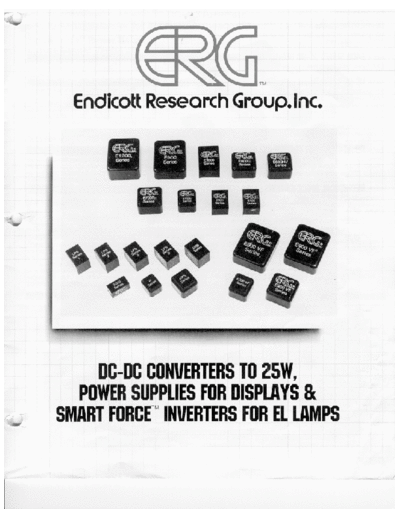
Image preview - the first page of the document

>> Download ERG_DC_DC_Converters documenatation <<
Text preview - extract from the document
SEE NEXT PAGE FOR DETAILS
                                        +                   Typical Input Filter Configurations

                  10uf                      (1)
                                                   These filtering configurations will minimize the
                   to                              amount of switching ripple reflected on the DC
                                   IN
                 200uf                             input.

                                        -          The specific component values required depend on
                                                   the input current and the impedance of the input
                                                   voltage source.

                                                   These filtering configurations will minimize the
                                        +          amount of switching ripple reflected on the DC
                                            (2)    input.
      10uf                0.01uf
       to                    to    IN              Figure (1) is the least effective, but is generally
     200uf                 0.1uf                   adequate in most switching systems.

                                        -          Figure (2) provides a 50% reduction in higher
                                                   frequency components of the input ripple.

                                                   Figure (3) provides adequate input filtering for
                                                   analog systems.
             0.1 to 1mh
                                        +          Figure (4) provides a 50% reduction in input
                                             (3)   ripple amplitude compared with figure (3).
                  10uf
                   to              IN
                 200uf

                                        -


             0.1 to 1mh
                                        +
                                            (4)
0.01uf             10uf
   to               to             IN
 0.1uf            200uf

                                        -
◦ Jabse Service Manual Search 2024 ◦ Jabse Pravopis ◦ onTap.bg ◦ Other service manual resources online : Fixya ◦ eServiceinfo