Service Manuals, User Guides, Schematic Diagrams or docs for : Keithley 2001 ds MC14094B
<< Back | HomeMost service manuals and schematics are PDF files, so You will need Adobre Acrobat Reader to view : Acrobat Download Some of the files are DjVu format. Readers and resources available here : DjVu Resources
For the compressed files, most common are zip and rar. Please, extract files with Your favorite compression software ( WinZip, WinRAR ... ) before viewing. If a document has multiple parts, You should download all, before extracting.
Good luck. Repair on Your own risk. Make sure You know what You are doing.
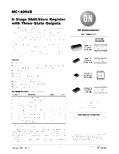
Image preview - the first page of the document

>> Download MC14094B documenatation <<
Text preview - extract from the document
MC14094B

8-Stage Shift/Store Register
with Three-State Outputs
   The MC14094B combines an 8-stage shift register with a data latch
for each stage and a 3-state output from each latch.
   Data is shifted on the positive clock transition and is shifted from the
seventh stage to two serial outputs. The QS output data is for use in                               http://onsemi.com
high-speed cascaded systems. The QS output data is shifted on the
following negative clock transition for use in low-speed cascaded                                                           MARKING
                                                                                                                            DIAGRAMS
systems.
   Data from each stage of the shift register is latched on the negative                                               16
                                                                                                           PDIP-16
transition of the strobe input. Data propagates through the latch while                                                         MC14094BCP
                                                                                                          P SUFFIX
strobe is high.                                                                                           CASE 648
                                                                                                                                 AWLYYWW
   Outputs of the eight data latches are controlled by 3-state buffers                                                  1
which are placed in the high-impedance state by a logic Low on
Output Enable.                                                                                                              16
                                                                                                          SOIC-16                     14094B
Features                                                                                                  D SUFFIX                   AWLYWW
◦ Jabse Service Manual Search 2024 ◦ Jabse Pravopis ◦ onTap.bg ◦ Other service manual resources online : Fixya ◦ eServiceinfo