Service Manuals, User Guides, Schematic Diagrams or docs for : Keithley 2001M CDROM Digital Multimeters - Data Acquisition - Switch Systems Product Information CD_Content pdfs accessories 4674-2,0

<< Back | Home

Most service manuals and schematics are PDF files, so You will need Adobre Acrobat Reader to view : Acrobat Download Some of the files are DjVu format. Readers and resources available here : DjVu Resources
For the compressed files, most common are zip and rar. Please, extract files with Your favorite compression software ( WinZip, WinRAR ... ) before viewing. If a document has multiple parts, You should download all, before extracting.
Good luck. Repair on Your own risk. Make sure You know what You are doing.


Image preview - the first page of the document
4674-2,0


>> Download 4674-2,0 documenatation <<

Text preview - extract from the document
Test Fixtures

 Device Compatibility                     3323A         3327   8006       8007    8008     8009
 Sheet Resistance                                                                  I         I
 Volume Resistance                                                                 I         I
 Axial Devices                               I                  I
 Chip Devices                                            I
 T0 18 Packages                4-Lead                           I
 T0 5 Packages                 4-Lead                           I
                               8-Lead                           I
 Dual In-Line Packages        24-Lead                                      I
                              28-Lead                           I
                              48-Lead                                      I
 Prototyping Board                                                         I


 Instrument Compatibility                 3323A         3327   8006       8007    8008     8009
 Characterization Systems     4200-SCS                          I          I
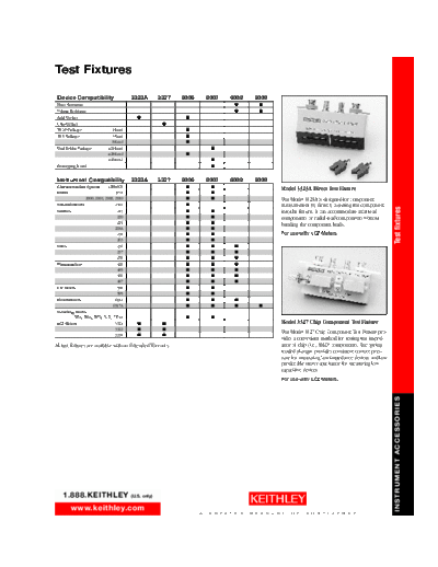
                                                                                                     Model 3323A Direct Test Fixture
 DMMs                              197A                         I          I
                 2000, 2001, 2002, 2010                         I          I                         The Model 3323A is designed for component
 Nanovoltmeters                    2182                         I                                    measurement by directly inserting the component


                                                                                                                                                        Test fixtures
 Sources                            213                         I          I                         into the fixture. It can accommodate axial-lead
                                    220                         I          I                         components or radial-lead components without
                                    224                         I          I                         bending the component leads.
                                   228A                         I          I
                                    230                         I          I                         For use with: LCZ Meters.
                                    263                         I          I
 SMUs                               236                         I          I       I
                                    237                         I          I       I
                                    238                         I          I       I
 Picoammeters                       428                         I          I       I
                                    485                         I          I       I
                                    486                         I          I       I
                                    487                         I          I       I
 C-V Meters                         590                         I          I
                                    595                         I          I
 Electrometers                     6514                         I          I       I
                                  6517A                         I          I       I         I
 Switching Matrix
          707A, 708A, 7072, 7172, 7174A                         I          I
 LCZ Meters                        3321      I           I                                           Model 3327 Chip Component Test Fixture
                                   3322      I           I
                                   3330      I           I
                                                                                                     The Model 3327 Chip Component Test Fixture pro-
                                                                                                     vides a convenient method for testing the imped-
All test fixtures are available with an Extended Warranty.                                           ance of chip (i.e., SMD) components. The spring-
                                                                                                     loaded plunger provides consistent contact pres-
                                                                                                     sure for measuring low impedance devices and low
                                                                                                     predictable stray capacitance for measuring low
                                                                                                     capacitive devices.
                                                                                                     For use with: LCZ Meters.


                                                                                                                                                        INSTRUMENT ACCESSORIES


    1.888.KEITHLEY                        (U.S. only)

         www.keithley.com
                                                                      A   G R E A T E R   M E A S U R E   O F   C O N F I D E N C E
                          Test Fixtures

                                                                                on Dual In-line Packages (DIPs) of 0.3 or 0.6 inch
                                                                                centers and up to 48 pins with the 24- or 48-pin
                                                                                socket. The prototyping board can be installed on
                                                                                the front panel for customized testing of packages
                                                                                with up to 72 pins.
                                                                                Accuracy is maintained to the DUT with isolation
                                                                                of more than 1T. Offset current for the 8007 is
                                                                                less than 1pA, while maximum signal voltage is
                                                                                200V with 1A peak current. A hinged cover pro-
                                                                                vides light-tight and shielded measurements. 72
                                                                                ferrite beads are also included for custom applica-
                                                                                tions when DC tests are performed on active
                                                                                devices and some decoupling is required.
                          Model 8006 Component Test Fixture                     Supplied with interlock cable, phototyping                 Model 8009 Resistivity Chamber
                          The Model 8006 Component Test Fixture                 board, and two input cables (each terminated
                          was designed specifically for making sensitive mea-   with twelve 3-slot triax plugs).                           The Model 8009 is a guarded test fixture for mea-
                          surements on standard package devices with mini-                                                                 suring volume and surface resistivities. It assures
Test fixtures


                          mal setup time. Individual components may be                                                                     good electrostatic shielding and high insulation
                          connected to one of eight device sockets, includ-                                                                resistance up to 1100V. The 8009 is designed for
                          ing axial, 4-, 8-, 10-, and 12-lead T0, and 28-pin                                                               safe operation with the 6517A. Opening the lid of
                          DIPs. Instrumentation can be easily integrated                                                                   the 8009 automatically turns off the 6517A voltage
                          through the 3-lug triax, BNC, or binding post con-                                                               source. The 8009 accommodates sheet samples
                          nectors on the rear panel.                                                                                       from 64mm to 102mm (21/2 to 4 in) in diameter
                                                                                                                                           and up to 3.2mm (1/8 in) thick. It maintains good
                          Signals from the test instruments are accessible at                                                              sample contact with uniform pressure (from 6 to
                          the test fixture's front panel. Mini jumper cables                                                               10 lbs depending on thickness) on smooth parallel
                          are provided to connect the signal to the appropri-                                                              samples.
                          ate device socket, which is also located on the
                          front panel. This unique patch-board design allows                                                               With the front panel switch on the 8009, toggle
                          for maximum versatility and the fastest possible                                                                 between volume and surface resistivity, with the
                          setup times.                                                                                                     6517A configured to calculate and display the
                                                                                Model 8008 Resistivity Chamber                             appropriate result automatically. The 8009 permits
                          The 8006 Test Fixture maintains accuracy through-                                                                direct measurement of volume resistivity up to
                          out the test circuit with greater than 100T           The 8008 Resistivity Chamber is a guarded                  1018-cm (on samples 0.1cm thick) and surface
                          (1014) path isolation, 4-wire connections, guard-     test fixture for measuring volume and surface resis-       resistivity up to 1017/square, in accordance with
                          ed jumpers, gold contacts and interconnects, and      tivities. It assures good electrostatic shielding and      ASTM procedures.
                          less than 100fA offset current. A hinged lid covers   high insulation resistance up to 1100V.
                                                                                                                                           Supplied with necessary cables to use with
                          the component panel to provide a light-tight and
                                                                                The 8008 accommodates sheet samples 64                     6517A, including Model 8607 Safety HV Dual
                          shielded measurement.
                                                                                to 102mm (21/2 to 4 in) in diameter and up to              Test Leads
                                                                                3.2mm (1/8 in) thick. It maintains good sample con-
                                                                                                                                           ENVIRONMENTAL LIMITS: Operating: 


◦ Jabse Service Manual Search 2026 ◦ Jabse PravopisonTap.bg ◦ Other service manual resources online : FixyaeServiceinfo