Service Manuals, User Guides, Schematic Diagrams or docs for : Keithley 2001M CDROM Digital Multimeters - Data Acquisition - Switch Systems Product Information CD_Content pdfs app_notes 3668-1,0
<< Back | HomeMost service manuals and schematics are PDF files, so You will need Adobre Acrobat Reader to view : Acrobat Download Some of the files are DjVu format. Readers and resources available here : DjVu Resources
For the compressed files, most common are zip and rar. Please, extract files with Your favorite compression software ( WinZip, WinRAR ... ) before viewing. If a document has multiple parts, You should download all, before extracting.
Good luck. Repair on Your own risk. Make sure You know what You are doing.
Image preview - the first page of the document
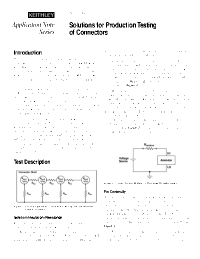
>> Download 3668-1,0 documenatation <<
Text preview - extract from the document
                                                       Number 2208


Application Note                                       Solutions for Production Testing
          Series                                       of Connectors

Introduction                                                                become shorted tomorrow in an environment with high heat and
                                                                            vibration, such as under the hood of a car.
As electronics have become increasingly pervasive, the
                                                                                   Isolation is typically tested by applying a voltage across
importance of electrical connectors has also increased dramatic-
                                                                            two pins in a connector and measuring the resulting current that
ally. Quality connectors are vital to ensuring overall product
                                                                            flows between them. The corresponding resistance from the test
reliability in applications ranging from motor vehicles to trans-
                                                                            is compared to a predetermined threshold value. If the resistance
atlantic telecom systems. This application note addresses many
                                                                            level is too low, the connector is rejected. Common threshold
of the issues involved in implementing a connector characteriza-
                                                                            levels range from 1M to 1T. The isolation resistance is
tion system.
                                                                            shown as Riso in Figure 1.
       The degree and type of electrical testing that connectors
                                                                                   When testing very high ohmic devices, the measured
undergo typically depends on how crucial they are to the overall
                                                                            resistance may change significantly in response to a change in
performance of the systems in which they're installed. Stringent
                                                                            the applied voltage, an effect known as the voltage coefficient of
electrical tests are often specified when high reliability is
                                                                            resistance. This effect makes it preferable to test high value
required. Obviously, connectors used in international telecommu-
                                                                            resistors with the constant voltage, measure current method. The
nications systems are more crucial than the serial port connector
                                                                            actual test voltage chosen depends on the capabilities of the
on the back of a desktop personal computer.
                                                                            instrumentation and the degree of current measurement sensitivi-
       The two most commonly measured parameters in connec-                 ty available. For a given resistance value, a higher voltage will
tor testing are isolation and continuity. Isolation measurements            result in a higher current signal, which can be measured with
are usually performed between each of the connector pins or                 higher resolution. Figure 2 illustrates the constant voltage
between the pins and the outer shell of the connector. Also,                method for measuring high resistances.
during connector manufacturing and testing (both mechanical
and environmental testing), the continuity may become
compromised. Testing the continuity of each pin ensures that                                                  RIsolation
once the connector is installed, the electrical signals will be
transmitted properly.                                                                                                              HI
                                                                                        Voltage
                                                                                                                            Ammeter
Test Description                                                                        Source

                                                                                                                                   LO
    Connector Shell

       Rpin1             Rpin2             Rpin3                RpinX
                  Riso              Riso              Riso                  Figure 2. Constant Voltage Method for Measuring High Resistance.


           Riso              Riso              Riso                  Riso
                                                                            Pin Continuity
                                                                            As long-term performance of connectors becomes increasingly
                                                                            important, the continuity performance from the input to the out-
Figure 1. Electrical equivalent of a connector showing pin continuity and   put of the connector will also become more important. Typically,
          isolation resistance.                                             continuity is tested by sourcing a constant current through the
                                                                            pin and measuring the corresponding voltage drop. Connector
Isolation (Insulation) Resistance                                           pins are often made from metal alloys, so the measurement result
Essentially, the isolation measurement verifies that none of the            is a very low resistance value. Pin continuity is shown as Rpin in
connector pins are shorted to each other. Given today's ever-               Figure 1.
shrinking circuit geometry and the higher frequencies of elec-                     Using high currents to test continuity has two advantages.
tronics, isolation is an important consideration for reliability and        First, using a sufficiently high test current ensures the resulting
minimizing crosstalk. A connector with no shorts today may                  voltage signal will be above the noise floor of the test system.
The ratio of the test current to the noise current will determine         2400 can output 210V, while the 2410 is capable of 1100V. Both
the signal-to-noise ratio and accuracy of the continuity test.            supplies are limited to 22W. These output ranges mean that only
Second, higher test currents can also serve as a stress test for          one measurement instrument is required for both isolation and
the connector. Often, the connector will be tested at a current           continuity measurements, which greatly reduces programming,
level higher than the rated current level in order to verify              cabling, and potential error sources.
performance margin.
                                                                                 Connectors typically contain many pins, so many measure-
       If stress testing is unnecessary, a digital multimeter             ment channels are required to test each pin. The most cost-
(DMM) with low voltage noise can be used to measure the pin               effective way of adding measurement channels is to include
resistance directly. Figure 3 illustrates how a current source and        switching in the test system. When switching is added, the user
voltmeter are used to measure resistance. Most instruments
                                                                          can connect the SourceMeter instrument to specific points on the
designed to measure low resistances have a built-in current
                                                                          connector for testing while simultaneously isolating other points.
source and voltmeter and can be configured to measure
                                                                          Also, if a PC is added to the system to control the instrument and
resistance with one instrument bus command or button on the
                                                                          switching, the entire connector test assembly can be automated,
front panel.
                                                                          eliminating the need for constant operator oversight. Figure 4
                                                                          illustrates a simple connector test configuration based on a
                                                                          SourceMeter instrument.
                                                         HI
         Current                                                                 A SourceMeter-based connector test system is both cost
         Source                        RContinuity   Voltmeter
                                                                          effective and easy to implement in terms of cabling, program-
                                                         LO               ming, and complexity. Systems like this can typically resolve
                                                                          signals as low as 10
◦ Jabse Service Manual Search 2026 ◦ Jabse Pravopis ◦ onTap.bg ◦ Other service manual resources online : Fixya ◦ eServiceinfo