Service Manuals, User Guides, Schematic Diagrams or docs for : Keithley 2001M CDROM Digital Multimeters - Data Acquisition - Switch Systems Product Information CD_Content pdfs data_sheets 3526-1,1
<< Back | HomeMost service manuals and schematics are PDF files, so You will need Adobre Acrobat Reader to view : Acrobat Download Some of the files are DjVu format. Readers and resources available here : DjVu Resources
For the compressed files, most common are zip and rar. Please, extract files with Your favorite compression software ( WinZip, WinRAR ... ) before viewing. If a document has multiple parts, You should download all, before extracting.
Good luck. Repair on Your own risk. Make sure You know what You are doing.
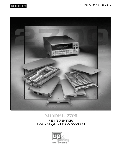
Image preview - the first page of the document
>> Download 3526-1,1 documenatation <<
Text preview - extract from the document
                    TECHNICAL DATA


   MODEL 2700
      MULTIMETER/
DATA ACQUISITION SYSTEM
M O D E L 2 7 0 0 M U LT I M E T E R / D ATA A C Q U I S I T I O N S Y S T E M


Table of Contents                                        Introduction
                                                         The Model 2700 61/2-digit Multimeter/Data Acquisition system blends Keithley's
                                                         high performance DMM technology, our switching expertise, and our data
 3   Overview
                                                         acquisition knowledge into a compact, affordable, easy-to-use package. This
 3   Front and Rear Panel Views                          technical data sheet provides a comprehensive overview of the system and
                                                         includes complete detailed specifications.
 3   Measurement Ranges
                                                         The Model 2700 Multimeter/Data Acquisition System consists of the 2700
 4   Measurement Control Module Capabilities             mainframe and a choice of five switch/control modules. The two-slot main-
 4   Module Capabilities Overview                        frame allows two different types of multiplexer or control modules to operate
                                                         simultaneously. Input modules can be mixed or matched to provide a broad
 5   Module Combination Selector Guide                   range of measurement, acquisition, and control capabilities.
 5   Channel Configuration Capabilities                  The Model 2700 provides up to 80 channels of multiplexed measurement and
 6   Scanning Capabilities                               control. Each channel can be configured independently. Settings can be con-
                                                         figured via the computer controller (over GPIB or RS-232) or the front panel of
 7   Triggering and I/O Capabilities                     the Model 2700 mainframe.
 7   Trigger Sources                                     The Model 2700's ActiveX-based start-up software, Xlinx, enables users to con-
                                                         figure the system, log multiple channels of data in real-time, troubleshoot any
 8   Alarm Limits
                                                         given channel, and send data directly to Excel or disk. Configuration is done in
 8   On-board Data Storage                               the familiar Windows "point-and-click" environment; therefore, there's no need
                                                         to program or write lines of code.
 9   Saving/Recalling a Setup
                                                         If you have any questions after reviewing this information, please contact your
 9   Power Failure Recovery
                                                         local Keithley representative or call one of our Applications Engineers at 1-800-
 9   Channel Monitor                                     552-1115 (U.S. only). Check Keithley's website (www.keithley.com) for the
                                                         names and numbers of representatives around the world.
 9   Measurement Performance
10   Filtering
10   Line Cycle Synchronization        Model 2700 System Diagram
                                                                                                                    MEASURE
10   NPLC                                                                                    Universal              DCV
                                                                                           Input Modules            Ohms
10   Offset Compensation                                            Model 2700                                      Temp
                                                                                                                    ACV
11   Temperature Measurements                                                                                       Freq
                                                                                                                    Current
                                                                                                                    Totalizer
12   Model 2700 Free Software
                                                                                                                    CONTROL
13   Calibration                                                                                                    Isolated Switching
                                                                                                                    Analog Output
14   Model 2700 Specifications                                                                                      Digital Output

17   Switch/Control Module
     Specifications


2
                                                                                                   TECHNICAL DATA


                                                                                                                            Overview
  Use mX+b or %       Measure the ratio      View a channel of        Built-in          Front panel input jacks simplify
scaling to convert    or average of two       interest without    linearization for    manual probing, troubleshooting,
sensor/transducer      input channels.         interrupting a     thermocouples,         and calibration. Built-in signal
  outputs directly                           scan by using the       RTDs, and         conditioning with 1000V isolation
 into engineering                            Channel Monitor        thermistors.      simplifies system configuration and
       units.                                     feature.                                ensures good measurements.


   Initialize the       Non-volatile           Manually step       Set the number       Familiar DMM-like front panel
system with one of     memory allows         through channels       of digits to be    scheme makes it easier to use on
     four fully        time-stamped               or scan         displayed as well     bench or rack. Select or change
  programmable         storage of 55k          automatically.       as the reading      functions with the simple push
set-up conditions.        readings.           Configure each             rate.                   of a button.
      System                                      channel
 configuration is                             independently.
  stored in non-
 volatile memory.


    Built-in digital I/O lines provide for           Trigger Link enables tightly        GPIB and RS-232
     control, external triggering, and           synchronized triggering with other       interfaces are
        HI/LO alarm/limit outputs.                instruments in large ATE systems          standard.


 A variety of measurement and control           Rugged 50-pin D-sub connectors         Build-in noise rejection circuitry
modules let you mix, match, and change          ensure dependability and quick           ensures stable, predictable
 input signals or control lines any time         setup/teardown in production                  measurements.
you like. Install up to two modules at a                   test racks.
   time to create up to an 80-channel
           "mini-ATE" system.


                                                                                                                                  3
M O D E L 2 7 0 0 M U LT I M E T E R / D ATA A C Q U I S I T I O N S Y S T E M


                                                                Measurement Ranges
                                                       1n        1
◦ Jabse Service Manual Search 2026 ◦ Jabse Pravopis ◦ onTap.bg ◦ Other service manual resources online : Fixya ◦ eServiceinfo