Service Manuals, User Guides, Schematic Diagrams or docs for : Keithley 2200 Quick Start Guide
<< Back | HomeMost service manuals and schematics are PDF files, so You will need Adobre Acrobat Reader to view : Acrobat Download Some of the files are DjVu format. Readers and resources available here : DjVu Resources
For the compressed files, most common are zip and rar. Please, extract files with Your favorite compression software ( WinZip, WinRAR ... ) before viewing. If a document has multiple parts, You should download all, before extracting.
Good luck. Repair on Your own risk. Make sure You know what You are doing.
Image preview - the first page of the document
>> Download Quick Start Guide documenatation <<
Text preview - extract from the document
Series 2200 power Supplies Quick Start Guide
Front Panel Operation
STEP 1 Setting the Output Voltage
1. Press V-Set.
2. Use the arrow keys, numeric keypad, or the navigation wheel to enter the desired voltage
output value.
3. Press Enter to set the voltage.
STEP 2 Setting the Current Limit
1. Press I-Set.
2. Use the arrow keys, numeric keypad, or the navigation wheel to enter the current limit.
3. Press Enter to set the current.
STEP 3 Turning on the Output
1. Press Output ON/OFF
Remote Operation
The following SCPI command example resets the power supply, sets the voltage output to 3.33V, the
current limit to 1.6A and turns the output on.
*RST
SOURCE:FUNC:MODE FIX
SOURCE:VOLT 3.33V
SOURCE:CURR 1.6A
SOURCE:OUTP:ON
Connecting a Device
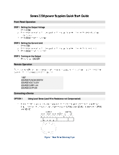
OPTION 1 Using Local Sense (Lead Wire Resistance not Compensated)
1. Install the shorting clip (included in accessories) on the rear panel terminal strip as shown in
Figure 1 below. You may also use jumpers between DRIVE+ and SENSE+, and between DRIVE-
and SENSE-.
Figure 1 Rear Panel Shorting Clips
2. Connect two wires from either the front panel binding posts, as shown in Figure 2 below, or the
rear panel DRIVE+ and DRIVE- terminals to your device under test.
Figure 2 Connecting a Device to the Front Panel
OPTION 2 Using Remote Sense (Lead Wire Resistance Compensated)
1. Remove any jumpers or the shorting clip on the rear panel terminal strip connectors between
DRIVE+ and SENSE+ and between DRIVE- and SENSE-.
2. Connect a pair of leads from SENSE+ and SENSE- to the device under test as shown in Figure 3
below. (NOTE: To assure system stability, use a jacketed, twisted-pair cable between the
remote sense terminals of the Series 2200 and the load.)
3. Connect a pair of leads from the DRIVE+ and DRIVE- to the device under test as shown, again, in
Figure 3.
Figure 3 Connecting a Device to the Rear Panel
◦ Jabse Service Manual Search 2026 ◦ Jabse Pravopis ◦ onTap.bg ◦ Other service manual resources online : Fixya ◦ eServiceinfo