Service Manuals, User Guides, Schematic Diagrams or docs for : Keithley 3940 3940_900_01A
<< Back | HomeMost service manuals and schematics are PDF files, so You will need Adobre Acrobat Reader to view : Acrobat Download Some of the files are DjVu format. Readers and resources available here : DjVu Resources
For the compressed files, most common are zip and rar. Please, extract files with Your favorite compression software ( WinZip, WinRAR ... ) before viewing. If a document has multiple parts, You should download all, before extracting.
Good luck. Repair on Your own risk. Make sure You know what You are doing.
Image preview - the first page of the document
>> Download 3940_900_01A documenatation <<
Text preview - extract from the document
onfains crating srmafion
Publication Date: March 1991
Document Number: 3940-900-01 Rev. .A
WARRANTY
Keithley Instruments, Inc. warrants this product to be free from defects in material and workmanship for a
period of 1 year from date of shipment.
Keithley Instruments, Inc. warrants the following items for 90 days from the date of shipment: probes, cables,
rechargeable batteries, diskettes, and documentation.
During the warranty period, we will, at our option, either repair or replace any product that proves to be de-
fective.
To exercise this warranty, write or call your local Keithley representative, or contact Keithley headquarters in
Cleveland, Ohio. You will be given prompt assistance and return instructions. Send the product, transporta-
tion prepaid, to the indicated service facility. Repairs will be made and the product returned, transportation
prepaid. Repaired or replaced products are warranted for the balance of the original warranty period, or at
least 90 days.
LIMITATION OF WARRANTY
This warranty does not apply to defects resulting from product modification without Keithley's express writ-
ten consent, or misuse of any product or part. This warranty also does not apply to fuses, software, non-re-
chargeable batteries, damage from battery leakage, or problems arising from normal wear or failure to follow
instructions.
THIS WARRANTY IS IN LIEU OF ALL OTHER WARRANTIES, EXPRESSEDOR IMPLIED, INCLUDING
ANY IMPLIED WARRANTY OF MERCHANT ABILITY OR FITNESS FOR A PARTICULAR USE. THE
REMEDIES PROVIDED HEREIN ARE BUYERS SOLE AND EXCLUSIVE REMEDIES.
NEITHER KEITHLEY INSTRUMENTS, INC. NOR ANY OF ITS EMPLOYEES SHALL BE LIABLE FOR
ANY DIRECT, INDIRECT, SPECIAL, INCIDENTAL OR CONSEQUENTIAL DAMAGES ARISING OUT
OF THE USE OF ITS INSTRUMENTS AND SOFTWARE EVEN IF KEITHLEY INSTRUMENTS, INC., HAS
BEEN ADVISED IN ADVANCE OF THE POSSIBILITY OF SUCH DAMAGES. SUCH EXCLUDED DAM-
AGES SHALL INCLUDE, BUT ARE NOT LIMITED TO: COSTS OF REMOVAL AND INSTALLATION,
LOSSESSUSTAINED AS THE RESULT OF INJURY TO ANY PERSON, OR DAMAGE TO PROPERTY.
INSTRUMENTS
Instruments Division, Keithley Instruments, Inc. l 28775 Aurora Road l Cleveland, Ohio 44139 * (216) 248-0400 l Fax: 248-6168
WEST GERMANY: Keithky Instruments CmbH l Heiglhofstr. 5 l Munchen 70 l 089-71002-O l Telex: 52-12X% l Fax: 089-7100259
GREAT BRITAIN: Koitbley Instruments, Ltd. l The Minster l St?, Portman Road l Reading, Berkshire RG 3 IEA l 01144 734 575 666 l Fax: 01144 734 596 469
FRANCE Keitbky Instruments SARL l 3 Allee des Garays . B.P. 60.91124 Palaiseau/Z.I. l I-6-0115 155. Telex: 600 933 l Fax: 1-6.0117726
NIXHERLANDS: Keithley Instruments BV l Avelingen West 49 l 4202 MS C&in&an l P.O. Box 559 l 4200 AN Gortnchem .0X+0-35333. Telex: 24 684 l Fax: 01830-30821
SWITZERLAND: Keithley Instruments SA 0 Kriesbachstr. 4 l t%W Dubendorf l 01-821-9444 l Telex 828 472 l Fax: 0222-315366
AUSTRIA: Keitbley Instruments GesmbH l Rosenhugelstrasse 12 l A-1120 Vienna l (0222) 84 65 48 e Telex: 131677 l Fax: (0222) 8403597
ITALY: Keitbley Instruments SRL l Vi&S. Gbnignano 4/A -20146 Mtlano .02-4120360 or M-4156540 l Fax 02-4121249
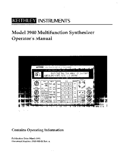
Operator's Manual
Model 3940
Multifunction Synthesizer
01991, Keithley Instruments, Inc.
All Rights Reserved
Instruments Division
Cleveland, Ohio, U. S. A.
Document Number: 3940-900-01
All Keithley product names are trademarks or registered trademarks of Keithley Instruments, Inc.
Other brand and product names are trademarks or registered trademarks of their respective holders.
Safety Precautions
The following safety precautions should be observed before using the Model 3940 Multifunction Synthesizer and any
associated instruments.
This instrument is intended for use by qualified personnel who recognize shock hazards and are familiar with the safety
precautions required to avoid possible injury. Read over this manual carefully before using the instrument.
Exercise extreme caution when a shock hazard is present at the test circuit. The American National Standards Institute
(ANSI) states that a shock hazard exists when voltage levels greater than 30V rms or 42.4V peak are present. A good
safety practice is to expect that hazardous voltage is present in any unknown circuit before measuring.
Inspect the connecting cables and test leads for possible wear, cracks, or breaks before each use.
For maximum safety, do not touch the test cables or any instruments while power is applied to the circuit under test.
Turn off the power and discharge any capacitors before connecting or disconnecting cables from the instrument.
Do not touch any object which could provide a current path to the common side of the circuit under test or power line
(earth) ground. Always make measurements with dry hands while standing on a dry, insulated surface capable of with-
standing the voltage being measured.
Instrumentation and accessories should not be connected to humans.
Table of Contents
SECTION 1- General Information
1.1 INTRODUCTION .............................................................. l-l
1.2 FEATURES ................................................................... l-l
1.3 WARRANTYINFORMATION .................................................... l-2
1.4 MANUALADDENDA .......................................................... l-2
1.5 SAFETY TERMS AND SYMBOLS .................................................. l-2
1.6 UNPACKING AND REPACKING ................................................. l-2
1.6.1 Unpacking ................................................................. l-2
1.6.2 Shipment Contents ........................................................... l-2
1.6.3 Operator'sManual ........................................................... l-2
1.6.4 Repacking For Shipment ....................................................... l-2
1.7 OPTIONAL ACCESSORIES ...................................................... l-3
1.8 SPECIFICATIONS ............................................................. l-3
SECTION 2- Getting Started
2.1 INTRODUCTION .............................................................. 2-l
2.2 INSTALLATION .............................................................. 2-1
2.2.1 InstallationLocation.. ........................................................ 2-l
2.2.2 Fan.. ..................................................................... 2-l
2.3 LINE VOLTAGE SUPPLY ........................................................ 2-2
2.3.1 Line Voltage Selector Switch .................................................... 2-2
2.3.2 Line Receptacle Connection ..................................................... 2-2
2.3.3 LineFuse .................................................................. 2-2
2.4 KANDLINGPRECAUTIONS ..................................................... 2-3
2.5 BASICOPERATION ............................................................. 2-3
2.5.1 FrontPanelSummary ......................................................... 2-3
2.5.2 Typical Test Connections ...................................................... 2-3
2.5.3 Operating Examples .......................................................... 2-5
SECTION 3 - Operation
3.1 INTRODUCTION .............................................................. 3-l
3.2 FRONT PANEL AND REAR PANEL DESCRIPTION ................................... 3-l
3.2.1 Front Panel Description ........................................................ 3-l
3.2.2 RearPanelDescription ........................................................ 3-12
3.3 Input and Output Connections .................................................... 3-14
3.3.1 InputConnections ........................................................... 3-14
3.3.2 OutputConnections .......................................................... 3-15
3.4 STARTUP .................................................................... 3-16
3.5 OPERATING PROCEDURES ..................................................... 3-17
3.5.1 Setting Parameters Using Numeric Keys ........................................... 3-17
3.5.2 Setting Parameters with MODIFY ................................................ 3-18
3.5.3 ErrorCodes ................................................................ 3-18
3.5.4 UnitsConversion ............................................................ 3-22
3.5.5 Frequency Programming ....................................................... 3-22
3.5.6 Amplitude Programming ...................................................... 3-23
3.5.7 DC Offset Programming ....................................................... 3-23
3.5.8 AC Amplitude and DC Offset Relational Restrictions ................................. 3-24
3.5.9' Waveform Selection, Square-Wave Duty Factor, and Synchronous Output .................. 3-26
3.5.10 Oscillation Mode and Trigger Source Selection ...................................... 3-28
3.5.11 Mark, Space, and Phase Parameter Programming .................................... 3-29
3.5.12 StopLeveland~S~C ........................................................ 3-32
3.5.13 SynchronousOperation ....................................................... 3-34
3.5.14 Frequency Sweep Operation .................................................... 3-34
SECTION 4 - GPIB Interface
4.1 INTRODUCTION .............................................................. 4-l
4.1.1 GPIBOverview .............................................................. 4-l
4.1.2 Major GPIB Specifications ...................................................... 4-l
4.1.3 Bus Line Signals and Operation .................................................. 4-2
4.1.4 GPIBHandshaking ........................................................... 4-2
4.1.5 Data Transfer Example ........................................................ 4-3
4.1.6 BasicTalkerFunctions ......................................................... 4-3
4.1.7 Basic Listener Functions ....................................................... 4-4
4.1.8 BasicControllerFunctions ...................................................... 4-4
4.1.9 Multi-Line Interface Messages ................................................... 4-4
4.2 OVERVIEW OF MODEL 3940 GPIB INTERFACE ...................................... 4-6
4.2.1 Introduction ................................................................ 4-6
4.2.2 Specifications ............................................................... 4-6
4.3 MODEL 3940 PROGRAM CODES .................................................. 4-13
4.3.1 Model 3940 Parameter-Setting Messages ........................................... 4-13
4.3.2 Model 3940 Inquiry Messages ................................................... 4-26
4.4 TYPICAL EXECUTION TIMES .................................................... 4-35
4.5 PROGRAM CODE SUMMARY TABLE .............................................. 4-40
4.6 SAMPLEPROGRAMS .......................................................... 4-45
List of Illustrations
SECTION 2- Getting Started
Figure 2-l FrontPanelSummary...................................................... 2-4
Figure 2-2 Typical Test Connections . . . . . . . . . . . . . . . . . . , . . . . . . . . . . . . . . . . . . . . . . . . . . . . . . . . 2-5
SECTION 3- Operation
Figure 3-l FrontPanel .............................................................. 3-2
Figure 3-2 RearPanel .............................................................. 3-12
Figure 3-3 Logic Input Circuits ....................................................... 3-14
Figure 3-4 Analog Input Circuit ....................................................... 3-14
Figure 3-5 Main Synthesizer Sync Output ............................................... 3-15
Figure 3-6 Sub Synthesizer Sync Output ................................................ 3-15
Figure 3-7 Sweep Marker and Sync Outputs ............................................. 3-15
Figure 3-8 Relational Range for Allowed AC Amplitude Voltage and DC Offset Voltage ............ 3-25
Figure 3-9 Phase Relationship Between Waveform and Synchronous Output ..................... 3-27
Figure 3-10 BURSTOscillation ........................................................ 3-28
Figure 3-l 1 TriggerOscillation ........................................................ 3-29
Figure 3-12 GateOscillation .......................................................... 3-29
Figure 3-13 Waveforms and Phase Definitions ............................................. 3-31
Figure 3-14 Waveform Examples with Hold Stop Level ...................................... 3-32
Figure 3-15 Waveform Examples with Reset Stop Level ...................................... 3-32
Figure 3-16 Phase Sync Operation ...................................................... 3-33
Figure 3-17 Phase Relationship after Phase Sync ............................................ 3-33
Figure 3-18 Sweep Frequency and Sweep Output ........................................... 336
Figure 3-19 SweepOperation ......................................................... 3-37
SECTION 4 - GPIB Interface
Figure 4-l Interface Connector ....................................................... 4-2
Figure 4-2 Handshake Timing Diagram ................................................. 4-3
Figure 4-3 Data Transfer Example ..................................................... 44
Figure 4-4 Program Code Syntax ...................................................... 4-7
Figure 45 Response Output Format ................................................... 4-9
List of Tables
SECTION 2- Getting Started
Table 2-l FuseReplacement......................................................... 2-3
SECTION 3- Operation
Table 3-l Main Synthesizer Amplitude Range . . . . . . . . . . . . . . . . . . . . . . . . . . . . . . . . . . . . . . . . . . . 3-20
Table 3-2 Sub Synthesizer Amplitude Range . . . . . . . . . . . . . . . . . . . . . . . . . . . . . . . . . . . . . . . . . . . . 3-20
SECTION 4- GPIB Interface
Table 4-l Multi-Line Interface Messages ................................................ 4-5
Table 4-2 InterfaceFunctions.. ...................................................... 4-6
Table 4-3 BusDriverSpecifications ................................................... 4-6
Table 4-4 Responses to Interface Messages .............................................. 4-7
Table 4-5 StatusByte.. ............................................................ 412
Table 4-6 Main Synthesizer Parameter Setting Messages .................................... 4-13
Table 4-7 Sub Synthesizer Parameter Setting Messages ..................................... 4-16
Table 4-8 Main Synthesizer Trigger Parameter Setting Messages .............................. 4-18
Table 4-9 Main Synthesizer Sweep Parameter Setting Messages .............................. 420
Table 4-10 Miscellaneous Parameter Messages ............................................ 4-23
Table 4-l 1 ARB Waveform Write and Readout Messages .................................... 4-24
Table 412 Parameters Specific to GPIB ................................................. 4-25
Table 4-13 Main Synthesizer Parameter Inquiry Messages ................................... 4-26
Table 4-14 Sub Synthesizer Parameter Inquiry Messages .................................... 4-28
Table 4-15 Main Synthesizer Trigger Parameter Inquiry Messages ............................. 4-29
Table 416 Main Synthesizer Sweep Parameter Inquiry Messages .............................. 4-30
Table 4-l 7 Inquiry Messages for Miscellaneous Parameters .................................. 4-32
Table 4-18 Inquiry Messages for ARB Waveform Write and Readout Parameters .................. 4-33
Table 4-19 Inquiry Messages for Parameters Specific to GPIB ................................. 434
Table 420 Typical Execution Times .................................................... 4-35
Table 4-21 Program Codes Summary ................................................... 4-40
SECTION 1
General Information
1 .l INTRODUCTION Frequency, amplitude, waveform, and phase can be in-
dependently set on the sub synthesizer, which is not de-
pendent upon the main synthesizer. The sub synthesizer
The Model 3940 Multifunction Synthesizer is a multi- can also be used as a trigger oscillator for the main syn-
function oscillator integrated with two frequency synthe- thesizer.
sizers: the OHz to 2OMHz main synthesizer and the OHz
to 1OOkHzsub synthesizer. The Model 3940 can generate
the entire frequency band at a resolution of O.lmHz, with Since the sub synthesizer and the main synthesizer use
an accuracy of tippm. the same clock source, the phase will not deviate when
the frequency is set with a whole number ratio.
Five output waveforms, %,%,-rL,n,and\,are The Model 3940 uses a two-line, 40-character liquid crys-
available. In addition, arbitrary waveforms set with the tal display to display selected functions, parameters, and
GPlB (IEEE-4881interface can be generated by the main pertinent messages. Parameter settings are easily made
synthesizer. Maximum output voltage for all waveforms using both the numeric keys and the modify knob.
is 20V p-p (no load).
The Model 3940 is equipped with a standard GPIB
(IEEE-4881 interface, and can be programmed over the
Since frequencies are synthesized directly by a custom bus for the same operating modes and parameters that
LSI digital IC, accuracy and stability are high, and the fre- can be controlled from the front panel.
quency switching time is short. Mother advantage is the
continuity of phase at frequency switchover.
The Model 3940 can be used as a multiphase oscillator
when combined with multiple identical units and used
with the optional synchronous cable.
Frequency sweep, half-cycle unit bursts of up to 32,768
cycles, trigger oscillation, and gate oscillation are avail-
able with the main synthesizer. The square-wave duty 1.2 FEATURES
cycle is also variable. In addition, external signals can be
combined with the oscillator output to generate custom 1. Two integrated independent frequency synthesiz-
waveforms. ers: Main Synthesizer and Sub Synthesizer
l-l
SECTION 1
General Information
2. Wide bandwidth; tippm frequency accuracy; and The WARNING heading used in this manual explains
phase continuity at frequency switchover. dangers that might result in personal injury or death. Al-
ways read the associated information very carefully be-
Main Synthesizer: OHz to 2OMHz fore performing the indicated procedure.
(resolution: O.lmHz)
Sub Synthesizer: OHz to 1OOkHz
(resolution: O.lmHz) The CAUTION heading used in this manual explains
hazards that could damage the instrument card. Such
damage may invalidate the warranty.
3. Five output waveforms available: vb-L A,
and\,( sub syn th esizer and main synthesizer); ar-
bitrary waveforms, variable duty factor for square 1.6 UNPACKING AND REPACKING
waves (main synthesizer only).
4. External signals can be added to the main synthe- 1.6.1 Unpacking
sizer waveform output to synthesize additional
waveforms. After carefully unpacking the instrument from its ship-
5. Burst, trigger, gate oscillation, and frequency sweep ping carton, inspect it for any obvious signs of physical
function (main synthesizer only). damage. Report any such damage to the shipping agent
6. Multiphase oscillator operation with the use of the immediately. Save the original packing carton for storage
optional synchronous cable and additional Model or possible future shipment.
3940 units.
1.6.2 Shipment Contents
1.3 WARRANTY INFORMATION
The following items are included with every Model 3940
order:
Warranty information is located on the inside front cover
of this operator's manual. Should your Model 3940 re- Model 3940 Multifunction Synthesizer
quire warranty service, contact the Keithley representa- Model 3940 Operator's Manual.
tive or authorized repair facility in your area for further Power cord
information. When returning the instrument for repair, Fuse 2A, 25OV,5.2 x 20mm (contained in fuse holder as
be sure to fill out and include the service form at the back spare fuse)
of this manual in order to provide the repair facility with BNC to BNC signal cable
the necessary information. Additional accessories as ordered.
1.4 MANUAL ADDENDA 1.6.3 Operator's Manual
If an additional manual is required, order the manual
Any improvements or changes concerning the instru- package, Keithley part number 3940-900-00.The manual
ment or manual will be explained in an addendum in- package includes an operator's manual and any perti-
cluded with the unit. Be sure to note these changes and nent addenda.
incorporate them into the manual before using the unit.
1.6.4 Repacking For Shipment
1.5 SAFETY TERMS AND SYMBOLS
Should it become necessary to return the Model 3940 for
repair, carefully pack the unit in its original packing car-
The following safety terms and symbols are found on the ton or the equivalent. Be sure to use a cardboard box of
instrument or used in this manual. sufficient strength.
Include the following information:
A
The' symbol on the instrument indicates that the
user should refer to the operating instructions. o Advise as to the warranty status of the instrument.
l-2
SECTION 2
GeneralInformation
l Write ATTENTION REPAIR DEPARTMENT on the The Model 7051-2 is terminated with male BNC connec-
shipping label. tors on both ends.
l Fill out and include the service form located at the back
of this manual.
Model 7051-5 BNC-to-BNC Cable: The Model 7051-5 is
5OQ BNC to BNC cable (RG-58C) 5ft. (1.2m) in length.
1.7 OPTIONAL ACCESSORIES The Model 70515 is terminated with male BNC connec-
tors on both ends.
The following accessories are available for use with the
Model 3940.
Model 7051-10 BNC-to BNC Cable: The Model 7051-10is
similar to the Models 7051-2 and 70515 except that it is
Model 3949 Synchronous Cable: The Model 3949 allows
loft. in length.
multiple Model 3940 units to be connected together to
form a multiphase oscillator.
Model 7754-3 BNC-to-Alligator Cable: The Model
Models 3900-l and 3900-2 Rack Mounting Kits: The 7754-3 is a 3ft. (0.9m) 5OQ cable (RG-58C), terminated
Model 3900-2 mounts one Model 3940 in a standard 19 with a male BNC connector on one end and two alligator
inch rack. The Model 3900-2 mounts two Model 3940s clips on the other end.
side by side in a standard 19 inch rack. Both kits include
all necessary hardware for proper rack mounting of the
instruments. Model 7755 5OQ Feed-Through Terminator: The Model
7755 is a BNC to BNC adapter that is terminated with a
5OQresistor. VSWR is ~1.1, DC to 25OMHz.
Model 7007 Shielded IEEE-488 Cables: The Model
7007-l (lm, 3.3ft.j and Model 7007-2 (2m, 6.6ft.j can be
used to interface the Model 3940 to the IEEE488 bus.
1.8 SPECIFICATIONS
Model 7051-2 BNC-to-BNC Cable: The Model 7051-2 is Detailed Model 3940 specifications may be found in Ap-
5OQ BNC to BNC cable (RG-58C) 2ft. (0.6m) in length. pendix B.
l-3
SECTION 2
Getting Started
2.1 INTRODUCTION Be sure to install the unit in a location that satisfies these
temperature and humidity conditions. Also the environ-
ment must be free of dust and vibration, and the Model
This sections contains basic information on installation 3944 must not be exposed to direct sunlight.
and power line connections; it also provides typical sim-
ple operating examples.
The Model 3940 uses a line filter, but pulse noise or strong
magnetic or electric fields may cause incorrect operation
of the unit. Do not install the unit near a source of pulse
2.2 INSTALLATION noise or strong magnetic or electric fields.
The following paragraphs discuss Model 3940 installa-
The guard on the rear panel of the unit is designed to pro-
tion. In particular, use adequate care when installing the tect rear panel connectors and should not be used as a leg
unit. Improper installation will adversely affect the life,
for installation. Do not stand the unit vertically on the
reliability, and safety of the unit.
rear guard because it may fall over, causing instrument
damage or personal injury.
The Model 3940 weighs about 12 lbs. Be careful when car-
rying the unit or mounting it in a rack. 2.2.2 Fan
The Model 3940 is air-cooled by a fan. Insufficient air flow
may cause components in the unit to fail. Follow the in-
2.2.1 Installation Location structions given below.
The allowable ambient temperature and humidity CAUTION
ranges for the Model 3940 are. Observe the following precautions to pre-
vent damage to the unit:
Operating: 0" to 4O"C, 10 to 9O%RH l An air intake port is provided on the rear
Storage: -10" to SO'C, 10 to 8O%RH panel of the unit. Allow a space of at least
2-l
SECTION 2
Gettim Started
four inches between the rear panel and a WARNING
wall or other obstruction. Disconnect the power cord from the instru-
ment before changing the supply voltage
l An exhaust port is provided on the bottom setting.
panel of the unit. Install the unit on a rigid,
flat surface, and avoid installing it on soft
material such as a cushion. Be careful not to CAUTION
insert foreign material between the bottom Be sure to set the line voltage switch to the
of the unit and the surface underneath. An- correct position for the line power voltage to
other exhaust port is located on the top panel be used. Operating the instrument on an in-
of the unit. Be careful not to block the top correct voltage may cause damage to the unit.
port by placing an object on top of the unit.
* Avoid mounting two or more units vertically 2.3.2 Line Receptacle Connection
(for example, when using two or more units
synchronously). Placing one unit on top of Connect the supplied power cord to the rear panel LINE
another will obstruct the exhaust port. receptacle and to a grounded AC power receptacle sup-
plying the correct voltage.
l Dust collecting in the fan filter will prevent
sufficient air flow. In clean operating envi-
ronments, wash the filter with a mild deter- WARNING
gent every three months. When operating The Model 3940 is equipped with a 3-wire
the unit in a dusty environment, wash the fil- power cord that contains a separate ground
ter with a mild detergent at least once a wire and is designed to be used with
month. grounded outlets. When proper connections
are made, instrument chassis is connected to
l Immediately turn off the power to the unit if the power line ground. If the AC outlet is not
the fan ceases to operate. Operating the in- rounded, the rear panel ground terminal
strument with the fan inoperative may result L must be connected to safety earth
in damage to the instrument. b
ground using #18AWG (or larger) wire be-
fore use.
2.3 LINE VOLTAGE SUPPLY
2.3.3 Line Fuse
The Model 3940 operates with a lOOV, lZOV, 22OV, or
240V flO%, 48 to 62Hz, single-phase AC power supply. The line fuse, which is integral with the power line recep-
The power consumption is 84VA. tacle, protects the instrument from over-current situ-
ations. To replace the fuse, first disconnect the line cord,
then pry out the fuse compartment (immediately to the
left of the FUSE marking) with a small screwdriver. A
2.3.1 Line Voltage Selector Switch spare fuse is located in the compartment with the fuse be-
ing used. Replace the blown fuse only with the type listed
The LINE VOLTAGE SELECTOR switch on the rear in Table 2-1, then close the compartment.
panel allows you to change operating voltage of the
power supply. The standard setting of the switch is the
same as the voltage available in the country to which the WARNING
unit is shipped. Disconnect the line cord from the instru-
ment before replacing the fuse.
To change the power supply voltage, first disconnect the
line cord, and set the supply voltage switch in the correct CAUTION
position. Wait at least five seconds before turning the Use only a fuse of the rating listed in
power back on after turning it off. Table 2-1, or instrument damage may occur.
2-2
SECTION2
Geffitw Sfarfed
Table 2-l. Fuse Replacement 2.5 BASIC OPERATION
The following paragraphs summarize front panel operat-
ing controls, give typical test connections, and discuss
typical operating examples for the Model 3940.
2.5.1 Front Panel Summary
2.4 HANDLING PRECAUTIONS
Figure 2-l summarizes each front panel feature. For de-
A flat keyboard coated with a polyester film forms the tailed information on each operating feature, refer to Sec-
control panel surface of the Model 3940. Be careful not to tion 3.
damage the keyboard surface by cutting it with a sharp
instrument or touching it with a hot object.
2.5.2 Typical Test Connections
When the panel or casebecomes dirty, clean it with a soft
cloth. If the panel or case is too dirty for cleaning with a Figure 2-2 shows typical tests connections between the
dry cloth, dampen the cloth in mild detergent, and wipe Model 3940 main synthesizer and a DUT (sub synthesizer
the panel or casewith the damp clothNever use solvents connections are essentially the same). Note that 5OQchar-
such as thinner or benzene, or chemical dust cloths to acteristic impedance cables such as the Model 7051
avoid damaging case or front panel surfaces. should be used for all signal connections.
2-3
SECTION 2
Gettinf Started
r
SUB SYNTHESIZER OUTPUTS MAIN SYNTHESIZER OUTPUTS
SYNC OUT: TTL Sync signal
at programmed
frequency
FCTN OUT: Analop output FCTN OUT: Analog waveform
RCL: Recalls setups
I DATA I
GPIB: Prcqwns address 04, r Enters numeric
and terminator data
RUB OUT: Deletes current
number
I ENTRY I
FREQ: Sets frequency
(main crab)
AMPTD: Sets output amplitude
(main crab)
Adds shifted function OFFSET: Sets DC offset (main only)
to scme other keys FCTN: Sets waveform type
(main and sub)
MODE: Sets operating mode
(main only)
OSPL
L
Rehlrns display
to namsl
SWEEP
START FREQ. Programs start frequency
STOP FREQ. Prcgrams stop frequency
cm sets center frequency
Allows sub synthesizer CTR 4: Transfers marker to centa
SPAN: Sets span frequency
MKR: Sets marker frequency
SWEEP FCTN: Sets function
TRIG SWEEP TIME: Sets time
MAN: Manually trf~rs unit SWEEP OPR
START: Sixk single or
MARK: Selects number of continuous sweep
cscillatlon cycles SWEEP OFF: Cancels sweep mode
SPACE: Selects number of STATE: Sets sweep starV
stql cycles stop state
HOLD/FtESM: Pauses/resumes sweep
Figure 2-l. Front Panel Summary
2-4
SECTION 2
Getting Started
I
(Model 7051)
Model 3940 Main
Function
output
Figure 2-2. TypicaI Test Connections
2.5.3 Operating Examples 2. To directly enter a completely new numeric fre-
quency value, key in the desired number followed
The following examples give step-by-step instructions by the appropriate units key (Hz, kHz, or MHz). For
for setting basic Model 3940 operating parameters. All example, to enter a frequency of lO.lkHz, press: 1
examples except for Example 7 describe main synthesizer O.lkHz.
operation. Sub synthesizer operation for frequency, am- 3. To simply modify an existing frequency value, place
plitude, and function is similar to main synthesizer op- the cursor on the digit to be changed using 4 or b,
eration. Offset, mode, and sweep parameters do not ap- then use the MODIFY knob to set the digit to the de-
ply to the sub synthesizer. sired value. Repeat as necessary for all digits to be
changed. Note that you can press the STEPSIZE key
to multiply or divide by 2 or by 10.
4. To display the time period of the waveform fre-
Example I: Selecting the Waveform Type (Function)
quency, press the set key. You can then key in a new
time period or modify the existing period, if desired.
The waveform type can be selected using the FCTN key 5. Press Hz, kHz, or MHz to return to frequency dis-
as follows:
play.
6. Press DSPL to return to normal display.
1. Press FCTN and note that the instrument displays
the current function and the available functions.
2. Press the number key corresponding to the desired
function (O-61,or rotate the MODIFY knob until the Example 3: Setting the Output Amplitude
desired function number is displayed. For example,
press 3 to choose select the square wave function.
The waveform will immediately change to the se- Use the AMMD key to set the output voltage amplitude
lected function. as follows:
3. Press DSPL to return to the normal display mode.
1. PressAM??TD, and note that the instrument displays
the current amplitude and allowed amplitude range.
Example 2: Setting the Waveform Frequency or Period 2. To enter a completely new amplitude value in p-p
units, key in the numeric value, then press V or mV,
Use FREQ to set the frequency or period of the output as required. For example, to enter a 30mV p-p ampli-
waveform as follows: tude, press: 3 0 mV.
3. To simply modify the existing amplitude value, use
1. Press FREQ to enter the frequency programming the cursor keys and the MODIFY knob to set the
mode. The instrument will display the allowable fre- value as required.
quency range for the selected waveform. 4. kess DSPL to return to normal display.
2-5
SECTION 2
Getfing Started
Example 4: Programming the DC Offset 2. Press STOP FREQ and set the sweep stop frequency
as desired. For example, to program a 1OkHz stop
The OFFSETkey allows you to set the DC or average level frequency, press 10 kII2.
of the main synthesizer output waveform, as in the fol- 3. Press CTR and SPAN to view the center and span
lowing example: frequencies. With 1kHz and 1OkHz start and stop
frequencies, the center and span frequencies wilI be
1. Press OFFSET and note that the instrument displays 5.5kHz and 9kHz respectively. NOTE: If you change
the current offset value and allowed range. the center or span frequencies, the start and stop fre-
2. Either key in the desired offset, or use the MODIFY quencies will be automatically changed accordingly.
knob and cursor keys to change the value. 4. Press SWEEP FCTN, and choose the type of sweep.
3. Press DSPL to return to normal display. For example, press 2 to select a linear, ascending
sweep type.
5. Press SWEEPTIME, and program the sweep time as
required. For example, press 5 set to program a five-
Example 5: Selecting the Operating Mode
second sweep time.
6. To generate a single sweep, press SINGL START.
The Model 3940 main synthesizer can be operated in con- The unit will generate one sweep based on selected
tinuous, burst, trigger, or gate modes. The operating sweep parameters.
mode can be set with the MODE key as in the following 7. To generate continuous sweeps, press SHIFT START
example: CONT. The Model 3940 will generate sweeps con-
tinuously based on selected sweep parameters.
1. Press MODE and note that the instrument displays 8. Press SWEEP OFF to stop a sweep.
the current mode and available modes (continuous,
burst, trigger, and gate).
2. Press the number of the desired mode (or rotate Example 7: Using the Sub Synthesizer
MODIFY to choose the desired operating mode).
3. Press DSPL to return to normal display. Sub synthesizer parameters can be programmed in the
same way as the equivalent main synthesizer. The steps
below demonstrate how to program the sub synthesizer
Example 6: Controlling Sweep Operation function, frequency, and amplitude.
The Model 3940 main synthesizer can be used to sweep 1. To program the sub synthesizer function, press SUB
across a desired frequency range. The SWEEPkeys allow FCTN, then choose the desired waveform.
you to program sweep parameters, while the SWEEP 2. Program the sub synthesizer frequency by pressing
OPR keys control sweep operation. Perform the steps be- SUB FREQ, then key in or modify the frequency, as
low to demonstrate basic sweep operation: required.
3. To set the sub synthesizer output amplitude, press
1. Press START FREQ, and key in or use MODIFY to set SUB AMPTD, then set the amplitude as needed
the sweep start frequency. For example, press 1 kHz 4. Press SUB DSPL to display sub synthesizer parame-
to program a 1kHz start frequency. ters.
2-6
SECTION 3
Operation
3.1 INTRODUCTION the value of each parameter and the range of permissible
parameter values.
This section contains detailed information on front panel
operation of the Model 3940. For detailed GPIB (IEEE-488 The keyboard includes a SHIFT key, which gives certain
bus) operation, refer to Section 4. other keys secondary functions. A key which is shaded
with the same color as the SHIFT key requires that you
press SHIFT first before accessing the function of that
particular key.
3.2 FRONT PANEL AND REAR PANEL
DESCRIPTION
The keyboard also includes the SUB key, which allows
you to control sub synthesizer parameters. Pressing SUB
3.2.1 Front Panel Description followed by FREQ, for example, allows you to set the fre-
quency of the sub synthesizer.
The front panel of the Model 3940 is shown in Figure 3-1.
The front panel is made up of a two-line, 40-character liq-
uid crystal display and a control panel with a built-in flat Most settings are maintained in battery backed-up mem-
keyboard. The liquid crystal display presents informa- ory. As a result, the Model 3940 automatically assumes
tion useful for the operation of the Model 3940, such as the previous settings when the power is first turned on.
3-1
SECTION 3
Operation
SYNTHESIZER
V3-1. Front Panel
Key Representations when the Model 3940 is in the sub
mode.
This section uses special representation such as [SHIFT],
[SUB], LMODIFYI, or [SIZE] in the explanation of certain [MODIMI Either key in the value using the
keys. This representation indicates the following: DATA keys or change a given setting
value with the MODIFY knob. The
EmI Press the applicable key after press- up/down step size when increment-
ing the SHIFI key to access the ing or decrementing a value is fixed
shifted key function. The liquid crys- at 1, and the cursor position is also
tal display indicates "SHIFT" in the fixed.
upper left comer when the Model
3940 is in the shift mode. [MODIFYI [SIZE] Either key in the value using the
DATA keys or change a given setting
wJa Press the applicable key after press- value with the MODIFY knob. You
ing the SUB key to put the Model can specify the digit to be modified
3940 in the sub mode, which allows by placing the cursor on the desired
you to set sub synthesizer parame- digit using 4 orb. In addition, you
ters. The liquid crystal display indi- can change the modify up/down in-
cates "SUB" in the upper left comer crement using the STEP SIZE key.
3-2
SECTION3
Otlerafion
Detailed Descriptions In the gate oscillation mode,?lL and 5 correspond
to gate on at falling edge and gate on at rising edge,
Each front panel feature is described below. The circled respectively.
number to the left of each description corresponds to the
appropriate number shown in Figure 3-l.
STOP LEVEL
EmI, [MODal
01 POWER ON/OFF (Power switch)
POWER controls AC power to the Model 3940.
The STOP LEVEL key allows you to select the out-
put level during the stop cycle for the burst oscilla-
Press this switch once to turn power on, and press tion, trigger oscillation, and gate oscillation modes
POWER a second time to turn power off. (the stop level does not apply to the continuous
mode). You can select HOLD or RESET: with
HOLD the waveform will stop at the oscillation
start phase; with RESET,the waveform wrll stop at
02 Display
The two-line, 40-character display shows parame-
the waveform center value.
When the oscillation mode is set to other than the
ter values and other important information during CONT mode, and the stop level is set to RESET,
operation. An active display also indicates that in- the upper frequency limit is restricted to 1MHz.
strument power is turned on.
MARK (Oscillafion cycle)
03 TRIG (Trigger keys for burst, trigger, orgate oscil-
la tion)
MODIFY] l%=l
The MARK key allows you to set the number of os-
The various TRIG keys are used during burst, trig- cillation cycles for the burst oscillation and trigger
ger, or gate oscillation. The trigger mode can be se- oscillation modes.
lected using the MODE key described below.
In the burst oscillation mode, oscillations will be
generated for the number of cycles programmed
MAN (Manual trigger) with the MARK key, after which oscillations will
be stopped for the number of cycles programmed
Press MAN to manually trigger the unit. In the with the SPACE key (seebelow). This on-off cycle
trigger oscillation mode, the trigger signal is gen- of oscillations will be repeated continuously.
erated each time this key is pressed. In the gate os-
cillation mode, the gate signal remains on as long In the trigger oscillation mode, oscillations will be
as MAN is pressed. generated for the programmed number of cycles
only when a trigger is applied. The permitted
To use only the manual trigger as the trigger sig- range of mark oscillation cycles is from 0.5 cycle to
nal, select EXT (external) p for the trigger source, 32,768 cycles, and the resolution is 0.5 cycle.
and disconnect the cable from the EXT TRIG IN
BNC connector.
SPACE (Stop cycle)
MODa E=JY
SOURCE {Trigger source)
[MODIFY] The SPACE key allows programming of the num-
ber of stop cycles for the burst oscillation mode. In
This key allows you to select the trigger source, the burst oscillation mode, oscillations will be gen-
which includes EXT/INT (external/internal) and erated for the number of cycles set with the MARK
I/& (falling edge/rising edge). Selecting EXT key, and the off or stop period will occur for the
will enable front panel triggering through the EXT number of cycles set with the SPACE key. This on-
TRIG IN BNC connector. Selecting INT will enable off cycle of oscillations will be repeated continu-
the internal trigger signal synchronized with the ously.
sub synthesizer output. Note that the front panel
MAN key is operational for both internal and ex- The permissible range of settings is from 0.5 cycle
ternal trigger sources. to 32,768 cycles with 0.5 cycle resolution.
3-3
SECTION 3
Operation
PHASE @fart/stop phase)
[MODIFY] [SIZE]
ENTRY keys
0 5
and period setting.
for information on frequency
The PHASE key allows programming of the start/
stop phase setting for the burst or gate oscillation
modes. The allowed phase range is from-360.0" to
360.0". START FREQ (Start fiequency~
[MODIW l-SIZE1
This phase parameter can also be used as a resume
phase for oscillation when using phase sync. The START FREQ key allows you to set the start
frequency of the frequency sweep. You can specify
a start frequency that is either higher or lower than
the stop frequency. The relationship between the
(SUE3)PHASE CSub SynthesizerPhase) start and stop frequency values determines the
[SUB], [MODIFYI [SIZE] sweep direction. If the start frequency is higher
than the stop frequency, the sweep will be per-
Pressing [SUB] Pl&4SE allows you to set the phase formed in a descending direction. If◦ Jabse Service Manual Search 2026 ◦ Jabse Pravopis ◦ onTap.bg ◦ Other service manual resources online : Fixya ◦ eServiceinfo