Service Manuals, User Guides, Schematic Diagrams or docs for : Keithley 3940 3940_902_01A
<< Back | HomeMost service manuals and schematics are PDF files, so You will need Adobre Acrobat Reader to view : Acrobat Download Some of the files are DjVu format. Readers and resources available here : DjVu Resources
For the compressed files, most common are zip and rar. Please, extract files with Your favorite compression software ( WinZip, WinRAR ... ) before viewing. If a document has multiple parts, You should download all, before extracting.
Good luck. Repair on Your own risk. Make sure You know what You are doing.
Image preview - the first page of the document
>> Download 3940_902_01A documenatation <<
Text preview - extract from the document
9 ultif unctio
mice mud
ontains Servicing Information
Publication Date: August 1991
Document Number: 3940-902-01 Rev. A
WARRANTY
Keithley Instruments, Inc. warrants this product to be free from defects in material and workmanship for a
period of 1 year from date of shipment.
Keithley Instruments, Inc. warrants the following items for 90 days from the date of shipment: probes, cables,
rechargeable batteries, diskettes, and documentation.
During the warranty period, we will, at our option, either repair or replace any product that proves to be de-
fective.
To exercise this warranty, write or call your local Keithley representative, or contact Keithley headquarters in
Cleveland, Ohio. You will be given prompt assistance and return instructions. Send the product, transporta-
tion prepaid, to the indicated service facility. Repairs will be made and the product returned, transportation
prepaid. Repaired or replaced products are warranted for the balance of the original warranty period, or at
least 90 days.
LIMITATION OF WARRANTY
This warranty does not apply to defects resulting from product modification without Keithley's express writ-
ten consent, or misuse of any product or part. This warranty also does not apply to fuses, software, non-re-
chargeable batteries, damage from battery leakage, or problems arising from normal wear or failure to follow
instructions.
THIS WARRANTY IS IN LIEU OF ALL OTHER WARRANT IES, EXPRESSEDOR IMPLIED, INCLUDING
ANY IMPLIED WARRANTY OF MERCHANTABILITY OR FITNESS FOR A PARTICULAR USE. THE
REMEDIES PROVIDED HEREIN ARE BUYERS SOLE AND EXCLUSIVE REMEDIES.
NEITHER KEITHLEY INSTRUMENTS, INC. NOR ANY OF ITS EMPLOYEES SHALL BE LIABLE FOR
ANY DIRECT, INDIRECT, SPECIAL, INCIDENTAL OR CONSEQUENTIAL DAMAGES ARISING OUT
OF THE USE OF ITS INSTRUMENTS AND SOFTWARE EVEN IF KEITHLEY INSTRUMENTS, INC., HAS
BEEN ADVISED IN ADVANCE OF THE POSSIBILITY OF SUCH DAMAGES. SUCH EXCLUDED DAM-
AGES SHALL INCLUDE, BUT ARE NOT LIMITED TO: COSTS OF REMOVAL AND INSTALLATION,
LOSSESSUSTAINED AS THE RESULT OF INJURY TO ANY PERSON, OR DAMAGE TO PROPERTY.
INSTRUMENT-S
Instruments Division, Keithley Instruments, Inc. 28775 Aurora Road Cleveland, Ohio 44139 (216) 248-0400* Fax: 248-6168
l l l
WF.ST GERMANY: Keitbley Instruments GmbH l Heiglhofstr. 5 l Munchen 70 l 089-71002-O l Telex: 52-12160 l Fax: 089-7100259
GREAT BRITAIN: Keitbky Instruments, Ltd. l The Minster l 58, P&man Road l Reading, Berkshire RG 3 X4 l 01144 734 575 666 l Fax: 01144 734 596 469
FRANCE: Keithky Instruments SARL l 3 Allee des Garays l B.P. 60.91124 PaIatseau/Z.I. . l-6-0115 155. Telex MI0 933 l Fax: 1-6-0117726
NETHERLANDS: Keithley Instruments BV l Avelingen West 49 l 4202 MS Gorinchem l P.O. Box 559 l 4200 AN Gorinchem l 01830-35333 l Telex: 24 684 l Fax: 01830-30821
SWITZERLAND: Keitbley Instruments SA l Kriesbacbstr. 4 l 8600 Dubendorf l 0X321-9444 l Telex 828 472 e Fax: 0222-315366
AUSTRIA: Keitbley Instruments GesmbH l Rosenhugektrasse 12 l A-1120 Vienna. (0222) 84 65 48. T&x: 131677 l Fax: (0222) 8403597
ITALY: Keitbley Instruments SRL l Vi& S. Giiano 4/A l 20146 MiIano l 02-4120360 or 02-4156540 l Fax 02-4121249
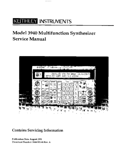
Service Manual
Model 3940
Multifunction Synthesizer
01991, Keithley Instruments, Inc.
All Rights Reserved
Instruments Division
Cleveland, Ohio, U. S. A.
Document Number: 3940-902-01
Safety Precautions
The following safety precautions should be observed before using the Model 3940 Multifunction Synthesizer and any
associated instruments.
This instrument is intended for use by qualified personnel who recognize shock hazards and are familiar with the safety
precautions required to avoid possible injury. Read over this manual carefully before using the instrument.
Exercise extreme caution when a shock hazard is present at the test circuit. The American National Standards Institute
(ANSI) states that a shock hazard exists when voltage levels greater than 30V rms or 42.4V peak are present. A good
safety practice is to expect that hazardous voltage is present in any unknown circuit before measuring.
Inspect the connecting cables and test leads for possible wear, cracks, or breaks before each use.
For maximum safety, do not touch the test cables or any instruments while power is applied to the circuit under test.
Turn off the power and discharge any capacitors before connecting or disconnecting cables from the instrument.
Do not touch any object which could provide a current path to the common side of the circuit under test or power line
(earth) ground. Always make measurements with dry hands while standing on a dry, insulated surface capable of with-
standing the voltage being measured.
Instrumentation and accessories should not be connected to humans.
HOW TO USE THIS MANUAL
Details procedures to verify that the instrument meets
stated specifications.
SECTION 1
Performance Verification
Describes basic operating principles for the various circuits in
the Model 3940.
SECTION 2
Principles of Operation
Covers fuse replacement, calibration and repair of the instru-
ment, and lists replacement parts.
SECTION 3
Service Information
WARNING
The information in this manual is intended for qualified serv-
ice personnel who can recognize possible shock hazards. Do
not attempt these procedures unless you are qualified to do so.
Table of Contents
SECTION 1 - Performance Verification
1.1 INTRODUCTION. ............................................................. l-l
1.2 ENVIRONMENTAL CONDITIONS ................................................ l-l
1.3 INITIALCONDTMONS ......................................................... l-l
1.4 LINEPOWERVOLTAGE.. ...................................................... l-1
1.5 RECOMMENDED TEST EQTJIPMENT .............................................. l-l
1.6 VERIEXATION PROCEDURES ................................................... l-2
1.6.1 Frequency and Duty Cycle Accuracy .............................................. l-2
1.6.2 AmplitudeAccuracy .......................................................... l-4
1.6.3 Frequency Response (Sine) ..................................................... 1-6
1.6.4 Frequency Response (Triangle, Sawtooth, Square) .................................... l-7
1.6.5 Frequency Response (Sub Sine) ............................ :. .................... l-8
1.6.6 Total Harmonic Distortion ..................................................... 1-8
1.6.7 DCVoltageAccuracy ......................................................... l-10
1.6.8 DCLevel(Square)andDCOffsetError(Sine) ....................................... l-11
SECTION 2 - Principles of Operation
2.1 INTRODUCTION .............................................................. 2-l
2.2 BLOCKDIAGRAM ............................................................ 2-1
22.1 ControlSection .............................................................. 2-1
2.2.2 Display and Keyboard Section ................................................... 2-1
2.2.3 Trigger Section .............................................................. 2-1
2.2.4 SweepSection ............................................................... 2-1
2.2.5 GMBInterface ............................................................... 2-l
2.2.6 SubSynthesizer ............................................................. 2-3
2.2.7 MainSynthesizer ............................................................ 2-3
2.2.8 PowerSupply ............................................................... 2-3
2.3 MAINSYNTHESIZERDESCRIl?TION .............................................. 2-3
2.3.1 Main Synthesizer Block Diagram ................................................. 2-3
2.3.2 D/AConverter .............................................................. 2-3
2.3.3 SquareWaveGenerator ....................................................... 2-3
2.3.4 Amplitude Control ........................................................... 2-3
2.3.5 OutputAmplifier ............................................................ 2-3
2.3.6 Calibration ................................................................. 23
2.4 SYNTHESIZER OPERATING PRINCIPLES .......................................... 2-5
SECTION 3 - Service Information
3.1 INTRODUCTION .............................................................. 3-1
3.2 LINEFUSEREPLACEMENT ..................................................... 3-1
3.3 CALIBRATION ............................................................... 3-1
3.3.1 EnvironmentalConditions ..................................................... 3-2
3.3.2 InitialConditions ............................................................ 3-2
3.3.3 LinePower............., ................................................... 3-2
3.3.4 Recommended Calibration Equipment ............... ; ............................. 3-2
3.3.5 Cover Removal .............................................................. 3-2
3.3.6 CalibrationAdjustments.. ..................................................... 3-3
3.3.7 CalibrationProcedures ........................................................ 3-6
3.3.8 CoverReplacement ........................................................... 3-8
3.4 FANFILTERCLEANING ........................................................ 3-9
3.5 RECHARGEABLE BATTERY REPLACEMENT ........................................ 3-9
3.6 REPAIR .... ................................................................. 3-9
3.6.1 Factory Service .............................................................. 3-9
3.6.2 PowerSupplyTestPoints ...................................................... 3-9
3.6.3 Board-LevelRepair ........................................................... 3-11
3.7 REPLACEABLEPARTS ......................................................... 3-11
3.7.1 PartsList .................................................................. 3-11
3.7.2 OrderingParts .............................................................. 3-11
APPENDICES
A Typical Data
B Model 3940 Specifications
List of Illustrations
SECTION 1 - Performance Verification
Figure l-l Connections to Timer/Counter ............................................... l-3
Figure l-2 ConnectionstoModel197ADMM ............................................ l-4
Figure l-3 Connections to Wideband AC DVM ........................................... l-6
Figure l-4 Connections to Audio Analyzer .............................................. l-9
SECTION 2 - Principles of Operation
Figure 2-l Overall Block Diagram ..................................................... 2-2
Figure 2-2 Main Synthesizer Block Diagram .............................................. 2-4
Figure 2-3 Frequency Synthesizer Address Generator Diagram .... ........................... 2-5
Figure 2-4 Address Generator Waveform ...... ......................................... 2-6
Figure 2-5 Waveform Memory and D/A Converter ........................................ 2-6
SECTION 3 - Service Information
Figure 3-1 CoverRemoval ........................................................... 3-3
Figure 3-2 Analog Board (NP-10375) Calibration Adjustments ................................ 3-4
Figure 3-3 Control Board (NP-21007) Calibration Adjustments ................................ 3-5
Figure 3-4 Sub Synthesizer Output Connections to Model 197A DMM .......................... 3-6
Figure 3-5 Main Synthesizer Output Connections to Timer/Counter ........................... 3-7
Figure 3-6 Main Synthesizer Output Connections to DMM .................................. 3-7
Figure 3-7 DMM Connections to DC OFS and GND Test Points ............................... 3-8
Figure 3-8 Power Supply Test Points ................................................... 3-10
Figure 3-9 Model 3940 Exploded View .................................................. 3-12
List of Tables
SECTION 1 - Performance Verification
Table l-1 Verification Equipment ..................................................... 1-2
Table l-2 Limits for Frequency and Duty Cycle Accuracy ................................... l-3
Table 1-3 Limits for Amplitude Accuracy ............................................... 1-5
Table 1-4 Limits for Frequency Response (Sine) .......................................... 1-7
Table 1-5 Limits for Frequency Response (Triangle, Sawtooth, Square) .......................... 1-7
Table l-6 Limits for Frequency Response (Sub Sine) ....................................... 1-8
Table 1-7 Limits for Total Harmonic Distortion .......................................... l-10
Table l-8 Limits for DC Voltage Accuracy .............................................. l-10
Table l-9 LimitsforDCLevel(Square)andDCOffsetError(Sine) ............................ l-11
SECTION 3 - Service Information
Table 3-l Recommended Line Fuses ................................................... 3-1
Table 3-2 Recommended Test Equipment for Calibration ................................... 3-2
Table 3-3 Board Level Repair Summary ................................................ 3-11
Table 3-4 Replaceable Parts ......................................................... 3-l 1
SECTION 1
Performance Verification
1 .I INTRODUCTION procedures. If the instrument has been subjected to ex-
tremes of temperature (outside the range specified in the
The procedures outlined in this section may be used to previous paragraph), additional time should be allowed
verify that the instrument is operating within the limits for internal temperatures to reach normal operating tem-
stated in the specifications. Performance verification may perature. Typically, it takes one additional hour to stabi-
be done when the instrument is first received to ensure lize a unit that is 10◦ Jabse Service Manual Search 2026 ◦ Jabse Pravopis ◦ onTap.bg ◦ Other service manual resources online : Fixya ◦ eServiceinfo