Service Manuals, User Guides, Schematic Diagrams or docs for : Keithley 605 605A(Model605)
<< Back | HomeMost service manuals and schematics are PDF files, so You will need Adobre Acrobat Reader to view : Acrobat Download Some of the files are DjVu format. Readers and resources available here : DjVu Resources
For the compressed files, most common are zip and rar. Please, extract files with Your favorite compression software ( WinZip, WinRAR ... ) before viewing. If a document has multiple parts, You should download all, before extracting.
Good luck. Repair on Your own risk. Make sure You know what You are doing.
Image preview - the first page of the document
>> Download 605A(Model605) documenatation <<
Text preview - extract from the document
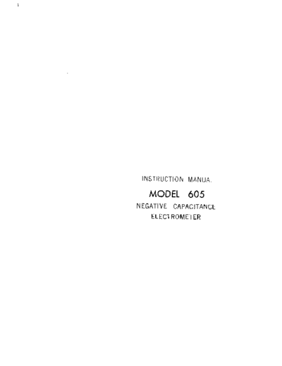
INSTRUCTION MANUAL
MODEL 605
NEGATIVE CAPACITANCE
ELECTROMETER
WARRANTY
We warrant each of our products to be free
from defects in material and workmanship. Our
obligation under this warranty is to repair or
replace any instrument or part thereof (except
tubes and batteries) which, within a year after
shipment, proves defective upon examination.
We will pay domestic surface freight costs.
To exercise this warranty, call your local
field representative or the Cleveland factory,
DDD 216-248-0400. You will be given assist-
ance and shipping instructions.
REPAIRS AND RECALIBRATION
Keithley Instruments maintains a complete re-
pair service and standards laboratory in Cleve-
land, and has an authorized field repair facility
in Los Angeles.
To insure prompt repair or recalibration serv-
ice, please contact your local field representa-
tive or the plant directly before returning the
instrument.
Estimates for repairs, normal recalibrations,
and calibrations traceable to the National Bu-
reau of Standards are available upon request.
0 1967 KEITHLEY INSTRUMENTS. INC.
MODEL 605 NEGATIVE CAPACITANCE ELECTROMETER TABLE OF CONTENTS
TABLE OF CONTENTS
Section Page Section Page
MODEL 605 SPECIFICATIONS . . . . . . .ii 4. MAINTENANCE. . . . . . . . . . . . 11
1. GENERAL DESCRIPTION. . . . . . . .l 4.-l. General. . . . . . . . . , . 11
4,-2. Parts Replacement. , . . . . 11
l-l. General. . . , . . . . .l 4,-3. Spec'ial Maintenance
l-2. Features . . . . . . . . .l Precautions. . . . . . . . . 11
4,-4.. Troubleshooting. . . , . . . 13
2. OPERATION. . . . . . . . . . . .3 4.-s. Procedures to Guide
Troubleshooting. . . . . . . 14,
2-l. Input Head . . . . . . , .3 4,-b. Calibration. . . . . . . . . 14,
2-2. Power Module . . . . . . .3
2-3. Operating Procedure. . . .3 5. ACCESSORIES. . . . . . . . , . . . 19
2-4~. Line Frequency Noise and
Minimum Response Speed . .5 5-l. Model 6051 Mounting
2-5. Capacitance Tuning . . . 6 Bracket. . . . . . . . . . . 19
2-6. Microelectrode Resistance 5-2. Model 6052 Integrator. . . . 19
Measurement. . . . . . . .7 5-3. Model 6053 Cable . . . . . . 19
2-7. Drift, Grid Current and
Ringing. . . . . . . . . . 7 6. REPLACEABLE PARTS. . . . . . . . . 21
3. CTRCUIT DESCKIPTION. . . . . . . . 9 6-1. Replaceable Parts List . . . 21
6-2. How to Order Parts . . . . . 21
3-l. General. . . . . . . . . . 9 Model 605 Replaceable
3-2. Input Head , . . . . . 9 Parts List . . . . . . . . . 22
3-3. Power Module . . . . . .lO Schematic Diagram
20387~ . . . . . . . . . . . 27
Green Repair and
Calibration Forms . . . . . . 29
gr Change Notice Last Page
9~ Yellow Change Notice sheet is included
only for instrument modifications
affecting the Instruction Manual.
0168~
GENERAL DESCRIPTION MODEL 605 NEGATIVE CAPACITANCE ELECTROMETER
TABLE 1. Model 605 Specifications.
INPUT RESISTANCE: Greater than W ohms.
INPUT CAPACITANCE NEUTRALIZATION: Up to 100 picofarads.
GRID CURRENT: Less than 10-L3 ampere without compensation.
RESPONSE AND NOlSE CHARACTERISTICS:
source Max. Rise Time,
Resistor, Min. f.ldb microseconds Max. Input Noise,"
megohms kilocycles (63%) (lo-90%) microvolts rms
" nnn
,~" 1 26
li 20 15 26 3;;
22 15 20 27 450
GAIN: 2 +5%.
VOLTAGE SUPPRESSION: Zero may be offset with IO-turn zero
control approximately flOO millivolts with respect to the input.
DRIFT: Less than 1 millivolt per hour after l-hour warmup;
less than 1 millivolt per "C;
less than lo-l4 ampere per day;
18s.~ than 10." ampere per "C.
DYNAMIC RANGE: iI volt at input.
MAXIMUM INPUT OVERLOAD: 3~100 volts.*'
OUTPUT RESISTANCE: Less than 1000 ohms.
CALIBRATION: Ramp required, may be Senerated by a triangle
wave (ramp) generator. An oscilloscope square wave calibrator
output may be used when integrated by Keithley Model 6052.
CONNECTORS: Input, Output and Calibrate: BNC. Indifferent
Electrode: Spring-loaded clip.
BATTERIES: Five TR286, one E12. 200 hours battery life.
DIMENSIONS, WEIGHT:
Input Head: 1%" high x 3%" wide x 2%" deep;
net weiSht. 9 ounces (3.foot power cable attached).
Power Module: 2" high x IO" wide x 5%" deep;
"et weight. 3 pounds.
ACCESSORIES SUPPLIED:
Model 6051 Mounting Bracket: Permits head to be supported by
ring stand and rod clamp.
BNC to Binding Post adapter, mating input co""ector.
~.~,__
*Noise measured between 10 cp* and ml KC with Amplifier tuned for
rated rise t,me.
-*Ma" reclwre *eVeral minutes to recover 10 soecified drift.
FIGUW 1. Kci~thley Model 605 Negative Capacitance Elect:rometer.
ii 0267
MODEL 605 NEGATIVE CAPACITANCE ELECTROMETER GENERAL DESCRIP'TION
SECTION 1. GENERAL DESCRIPTION
l-l. GENERAL. The Keithley Model 605 is a negative capacitance electrometer
a. What is a negative capacitance electrometer?
1. When a signal from a high impedance source is amplified, the capacitance of the
amplifier input and the connecting cable greatly degrades the signal rise time. For
example, with only ZO-picofarad shunt capacitance, a signal from a ZO-megohm source has
a 4,00-microsecond rise time.
2. A negative capacitance electrometer is useful for improving the rise time of signals
from high impedance sources. This is accomplished by applying in-phase feedback from
the output of a fixed gain amplifier to the input through a properly chosen capacitor.
Reducing the effective capacitance in the example to 1 picofarad, possible with the
Model 605, improves rise time to 20 microseconds.
1-2. FEATURES.
a. Battery operation allows the Model 605 to operate inside shielded areas without
introducing extraneous power line noise.
b. "Only three operating controls and a power switch are used: a lo-turn zero potentio-
meter which compensates for resting potentials and other dc offsets up to 100 millivolts;
a control on the input head for preliminary capacitance adjustment; and a fine capacitance
adjustment on the power module. The remote location of the fine capacitance control and
zero potentiometer allows adjustment without disturbing the experiment.
The Model 605 has grid current less than lo-l3 ampere and current drift less than
10!i4 ampere per day or per % without requiring a compensating adjustment. The low grid
current minimizes the possibility of polarizing the cell under study.
1n addition to low grid current, the Model 605 offers input resistance greater than
lof5 ohms, shunt capacitance adjustable to less than 1 picofarad with a 22 megohm source,
and short circuit noise less than 35 microvolts rms. The rise time of less than 20 micro-
seconds with a 22-megohm source permits faithful reproduction of pulse.
e. The power module has an input for a ramp calibrating s~ignal, allowing microelectrode
testing and optimum neutralization adjustment without disturbing the test preparation.
04,67R
OPERATION MODEL 605 NEGATIVE CAPACITANCE ELECTROMETER
TABLE 2. Input Head Controls and Terminals.
The table briefly describes each control and terminal, and indicates the paragraph which
contains instructions on the use of the control or terminal.
:ontrol or Terminal Functional Description Par.
:ord Connects the Input Head to the Power Module 2-3
Input Receptacle Bnc connector for signal input from microelectrode 2-3, 2
and indifferent electrode
Spring Lock Terminal Ground post for easy connection of indifferent 2-3
electrode
:apacitance Adjust For preliminary adjustments for neutralizing 2-3, 2
:ontro1 strav caDacitances on the inout circuitrv
TABLE 3. Power Module Controls and Connectors.
The table briefly describes each control and connector, and indicates the paragraph which
contains instructions on the use of the control or connector.
3ntrol or connector Functional Description Par.
3WER Switch Turns the power supply on and off 2-3
ERO Control Zeroes the output voltage. Also compensates for 2-3
resting potentials and other dc offsets.
INE CAP ADJ Control Used for neutralizing small changes of input capa- 2-3 2-t
citance
ROBE Receptacle Nine terminal mating connector for the Cord from 2-3
the Input Head
UTPUT Receptacle Bnc connector for output signal 2-3
AL Receptacle Bnc connector to receive ramp calibration signal, 2-3
allowing microelectrode testing and optimum capa-
citance neutralization adjustment
0767R
MODEL 605 NEGATIVE CAPACITANCE ELECTROMETER OPERATION
SECTION 2. OPERATION
2-l. INPUT HEAD. The Input Head is a small nine-ounce remote head that contains the
amplifier, enabling the Model 605 to be placed conveniently anywhere in a crowded experi-
mental system. The Head may be easily mounted in a standard rod and clamp system, using
the supplied mounting bracket. The Input Head is chrome plated to minimize corrosion
caused by salt solutions, and its tight fitting cover protects the amplifier from spilled
solutions.
2-2. POWER MODULE. The Power Module contains the operating controls and six mercury bat-
teries to operate the amplifier. Battery power allows the Model 605 to operate inside
shielded areas without introducing extraneous power line noise.
2-3. OPERATING PROCEDURE.
a. Connect the Input Head to the Power Module by connecting the nine-lead,shielded Cord
from the Input Head to the PROBE Receptacle on the Power Module. Lock the plug on the
Cord in place by rotating the outer jacket clockwise.
b. Connect the OUTPUT Receptacle on the Power Module to the input of an oscilloscope,
amplifier, potentiometric recorder, or some other suitable monitoring device. The OUTPUT
Receptacle is a bnc connector.
c. Apply a triangular wave to the CAL Receptacle on the Power Module.
1. Apply this signal with either a triangular wave generator, or, as shown in Figure 3,
with an oscilloscope square-wave calibrator output integrated by the Keithley Model 6052
Integrator. Turn the generator signal to off.
2. The CAL Receptacle is an input for a ramp calibrating signal, allowing microelectrode
testing and optimum neutralization adjustment without disturbing the test preparation.
(See paragraphs 2-5 and Z-6). The triangular signal is applied at the CAL Receptacle.
OUTPUT PROBE
Receptacle Receptacle POWERSwitch
(5106) (5103) (5101)
Spring Lock
Terminal (5102)
CAL Receptacle FINE CAP ADJ
Control (R131)
Receptacle Control (C101)
(X01)
FIGURE 2. Model 605 Controls and Terminals. Circuit designations refer to Replaceable
Parts List and schematic diagram.
0367R 3
OPERATION MODEL 605 NEGATIVE CAPACITANCE ELECTROMETER
This signal is differentiated by the RC combination of a 5 picofarad capacitor in the
Input Head, C103, and the resistance of the microelectrode connected from the Input to
the indifferent electrode through the bath. Thus, a current square wave is applied to
the input of the amplifier. Since, however, neither electrode has yet been connected,
an appropriate resistor, approximately 22 megohms, can be connected across the Input
to simulate the source resistance of a microelectrode.
d. Mount the Input Head with a standard rod and clamp system using the supplied mount-
ing bracket or just place the Head on the bench top.
e. Connect the Input Receptacle on the Input Head to the microelectrode or the calomel
cell. Shielded or unshielded cable may be used. For shielded connections, use the
mating bnc connector. For unshielded connections, insert a bare wire into the center ter-
minal of the Input Receptacle or use the banana jack adapter.
f. Connect the indifferent electrode to the bath or dish. The indifferent electrode
may be connected either to the shield of the mating bnc connector or to the Auxiliary
Spring Lock Terminal.
g. Short the tip of the microelectrode to the indifferent electrode by dipping the end
of the microelectrode into the salt bath.
m
FIGURE 3. The Power Module on the Model 605 has an Input for a Ramp Calibrating Signal,
Allowing Microelectrode Testing and Optimum Neutralization Adjustment Without Disturbing
any Test Preparation. The ramp signal may be obtained from a ramp generator, or, as
shown above, from an oscilloscope square-wave calibrator output integrated by the acces-
sory Keithley Model 6052 Integrator.
4, 0767R
MODEL 605 NEGATIVE CAPACITANCE ELECTROMETER OPERATION
h. Turn POWER Switch on the Power Module to "on". The POWEK Switch turns the power
supply on and off. The Supply is on when the red dot is visible through the switch knob.
1. Zero the oscilloscope and observe the output of the Model 605 on the oscilloscope.
i. Zero the output 01 the Model 605 with the ZERO Control on the Power Module. Besides
zeroing the output, the ZERO Control also compensates for resting potentials and other dc
offsets within a span of approximately 100 millivolts.
NOTE
There is no output overload protection on the Model 605.` A brief output short
circuit will not damage the Model 605, but will cause excessive drain on the
batteries.
k. Apply a triangular signal with the signal generator to the CAL Receptacle on the
Power Module and note the output on the oscilloscope. Compensate for stray capacitance
on the input by adjusting the Capacitance Adjust Control on the Input Head and the FINE
CAP ADJ Control on the Power Module. The Capacitance Adjust Control on the Input Head,
which is a 55-turn stable glass piston trinnner, because of its fine resolution and wide
range, is for preliminary adjustments. The FINE CAP ADJ Control is used for neutralizing
small changes of input capacitance, and, since it is on the Power Module, can be used
without disturbing the Input Head or the microelectrode.
1. Start with the FINE CAP ADJ Control at MAX (completely clockwise) and the
CapBcitance Adjust Control on the Input Head in the completely counter-clockwise
position.
2. Turn the Capacitance Adjust Control on the Input Head until the square wave rise
time on the oscilloscope decreases. When maximum tolerable overshoot is reached, the
input capacitance is nulled.
3. If fine capacitance adjustment is also necessary, use the FINE CAP ADJ Control.
1. Turn off the triangular signal to the CAL Receptacle. Do not disconnect the cable
between the signal generator and the CAL Receptacle. If the cable is disconnected, the
input capacitances will change and the Model 605 will no longer be tuned.
m. Insert the microelectrode into the cell and observe the resting potential, pulses
and the response to external stimulae. The microelectrode resistance can be checked
periodically by applying a triangular signal with the signal generator and observing the
magnitude of the output square wave (see paragraph 2-6).
NOTE
The Model 605 has a voltage gain of 2. Therefore, be sure to divide the output
signal by a factor of 2 when using an oscilloscope, recorder, etc.
Z-4,. LINE FREQUENCY NOISE AND MINIMUM RESPONSE SPEED. Line frequency noise may be a
problem in many measurement setups. There are several ways in which this noise can be
eliminated or minimized.
a. Using shielded cable at the Input Receptacle on the Input Head of the Model 605 re-
duces the noise pickup. However, use of a shielded cable at the input increases the mini-
mum obtainable rise time because of the distributed capacitance of the cable.
0767~ 5
OPERATION MODEL 605 NEGATIVE CAPACITANCE ELECTROMETER
b. A shielded room can also reduce line frequency noise. The shielded room is an impro-
vement over the shielded input cable because the rise time is not degenerated. However,
there still is line frequency pickup from the electronic equipment used in the experimental
setup. To reduce line pickup within a shielded room, a shielded cable can be used. As be-
fore, however, the rise time will increase.
c. A wire screen cage and an unshielded input cable is generally the best setup.
this setup almost all the line frequency noise can be excluded. The unshielded inpuzith
cable minimizes the distributed input capacitance and yields optimum rise time.
d. Mount the Input Head of the Model 605 as close to the preparation as possible. The
longer the lead the greater the capacitance to ground and, therefore, the greater the rise
time. Longer leads will produce more electrostatic ac pickup too: also, increased cable
length between Input Head and Power Module will increase rise time, and over 3 feet of
cable between the Model 605 OUTPUT and the oscilloscope may increase rise time.
2-5. CAPACITANCE TUNING. Rise time can be easily checked and optimized with the Model 605.
a. To tune for the desired rise time, connect the microelectrode to the indifferent elec-
trode by immersing the tip of the microelectrode into the bath, but not into the cell.
b. Apply a triangular voltage wave to the CAL Input on the Power Module (about 1000 cps
is good). Adjust the amplitude of this wave to read between 100 and 200 millivolts at the
Model 605 Output (one or two hundred millivolts is representative of the signal to be mea-
sured). A 5 picofarad capacitor in the Input Head, C103, and the resistance of the micro-
electrode form a differentiator to produce a square current pulse at the input of the
Input Head.
C. Tune for optimum rise time by making capacitance adjustments using the Capacitance
Adjust Controls.
1. There are two copsiderations to be taken into account before determining what
optimum tuning is.
a) Decreasing the rise time of the amplifier by tuning necessarily increases the
amplifier noise. The acceptable noise level can only be determined by the magnitude
of the signal being measured.
b) Rise time can be decreased by further neutralization but eventually overshoot and
oscillation result. Excessive overshoot causes :an erroneous reading for a fast impulse.
2. The Model 605 specified rise time (see Specifications, Table 1) can be achieved
only under the following conditions.
a) Set the FINE,CAP ADJ Control in the MAX Position (completely clockwise).
b) Achieve minimum distributed capacitance at the input by connecting a 10 or 22
megohm resistor with short leads from the input to the indifferent electrode.
Cl Adjust the Capacitance Control on the Input Head for minimum rise time.
6 0767R
MODEL 605 NEGATIVE CAPACITANCE ELECTROMETER OPERATION
d. To make intracellular potential measurements after tuning for the optimum rise
time, turn off the signal generator,* insert the tip of the microelectrode into the cell
and take readings. In like manner, tuning can be achieved after a measurement by taking
the tip of the microelectrode out of the cell while leaving it immersed in the bath,
applying the calibration signal and tuning.
2-6. MICROELECTRODE RESISTANCE MEASUREMENT.
a. To determine the resistance of the microelectrode, first connect a known resistor
of approximately 10 megohms between the input and the indifferent electrode. APPLY e
triangular wave to the CAL Receptacle. Choose a convenient wave amplitude and do not
change it. Observe the magnitude of the square wave at the OUTPUT Receptacle of the
Model 605. Repeat this procedure with a few other resistors with values of approximately
20, 50 or perhaps 100 megohms.
b. Next, connect the microelectrode to the Input Receptacle on the Input Head and short
the microelectrode to the indifferent electrode by immersing the tip of the microelectrode
into the bath, but not into the cell.
c. Do not change the amplitude of the applied triangular wave. Observe the magnitude
of the square wave at the OUTPUT Receptacle of the Model 605 and compare the amplitude of
this output with the amplitudes of the outputs of the known resistors. Determine the re-
sistance of the microelectrode by interpolation.
d. To make intracellular potential measurements upon determining the resistance of the
microelectrode, turn off the signal generator,+ ihsert the tip of the microelectrode into
the cell and take readings.
2-7. DRIFT, GRID CURRENT AND RINGING.
a. Drift is an inherent property of all electrometer tubes. The Model 605 uses an
electrometer tube, VlOl, at the input and has the expected drift characteristic.
The Model 605, however, must be warmed-up for at least one hour before the drift specifi-
cation can be met. The drift of the Electrometer is cumulative, after the proper
warm-up, and becomes moderately constant and quite predictable. HOWeVer, a severe over-
load at the input, in the range of 20 to 100 volts, will cause increased drift for several
minutes.
b. The Model 605 must be warmed-up for a short period,much less then an hour, before
grid current specification is realized. An overload between 20 and 400 volts at the in-
put will temporarily increase the grid current. The grid current after an overload or
just when the instrument is turned on will generally be about lo-l2 ampere.
c. Ringing at about 5 kc at up to 5 mv will occur in the electrometer tube when it is
shocked. This ringing will subside after one or two minutes. However, the normal intra-
cellular setup should be shock free because of the delicate microelectrode. Therefore,
there should be no shock induced upon the Model 605 under normal conditions.
yc Do not disconnect
-- the ----- Cable from the Power Module.
CAL This will change the input
capacitance. If it isnecessary to remove the signal generator, then disconnect the CAL
Cable from the generator and short that end. This will preserve the capacitance adjust-
ment.
0467~ 7
MODEL 605 NEGATIVE CAPACITANCE ELECTROMETER CIRCUIT DESCRIPTION
SECTION 3. CIRCUIT DESCRIPTION
3-1. GENERAL. The Keithley Model 605 is a negative capacitance eLectrometer. A variable
capacitor is applied from the output of the amplifier to the input to neutralize the inpur
capacitance and improve the signal rise time. The Input Head of the Model 605 contains a
th'ree-stage amplifier and the capacitive feedback networks. Within the Power Module is
the power supply of the instrument, the zero control network and the output divider rc-
1~130 K131
CAP ADJ (CIOI)
3-2. INPUT HEAD.
B . The amplifier is a three-stage amplifier that employs positive feedback to achieve
optimum signal rise time and negative feedback to obtain +2 gain stability,
b. A fraction of the output stage of the amplifier drives the cathode of the input
stage, electrometer tube VlOL.
c. The output of Tube VlOl drives the differential amplifier stage, transistors QlOl
and 4102, for amplification.
04,67R 9
CIRCUIT DESCRIPTION MODEL 605 NEGATIVE CAPACITANCE ELECTROMETER
d. The output of the differential amplifier, in turn, drives the emmitter-follower out-
put stage which is a bridge network composed of transistor Q103 and a floating power
supply, Bl04., B105 and B106.
e. Positive capacitive feedback, used to neutralize input capacitance, is fed through
the variable piston trimmer, ClOl, to the input of tube VlOl. The other end of the trimmer
is connected to a variable output divider, resistors R130 and Rl31, to achieve a FINE
CAPACITANCE ADJUSTMENT.
f. The potentiometer, RlO3, adjusts the frequency characteristics of the amplifier.
3-3. POWER MODULE.
a. The output divider resistors Rl28 and Rl29, which are 6 kilohm resistors, fix the
gain of the amplifier at +2. The gain of the amplifier is determined by the equation:
R128 + R129
"out = Vin ( equation 1
Rl29 )
Where Vout is the output voltage in volts;
Vin is the input voltage in volts;
and R128 and R129 are the divider resistors in ohms.
Since resistors Rl28 and R129 are both 6 kilohms, the equation becomes:
6 kJl + 6 kR
"out = Vin ( ) = 2Vin,
6 kR
and the gain is +2.
b. The ZERO Adjust Potentiometer, Rll4, and the Coarse Zero Adjust, P102, adjust the
dc voltage of the screen grid for tube VlOl. This control fixes the tube operating points.
Batteries Bl02 and B103 supply the power to the Coarse Zero Control PlO2, which, in
tu',,, determines the voltage at the screen grid of tube "101. Battery BlOl supplies
filament power to VlOl.
10 04,67R
MODEL 605 NEGATIVE CAPACITANCE ELECTROMETER MAINTENANCE
SECTION 4. MAINTENANCE
4,-l. GENERAL.
a. Section 4 contains the maintenance, troubleshooting and calibration procedures for
the Model 605 Negative Capacitance Electrometer. It is recommended that these procedures
be followed as close as possible to maintain the accuracy of the instrument.
b. The Model 605 requires no periodic maintenance beyond the normal care required of
high-quality electronic equipment.
4.-2. PARTS REPLACEMENT.
a. The Replaceable Parts List in Section 6 describes the electrical components of the
Model 605. Replace components only as necessary. Use only reliable replacements which
meet the specifications.
b. The electrometer tube, VlOl, is specially selected and aged; order only from Keithley
Instruments, Inc. In normal use, it should not need replacement pefore 10,000 hours of
operation. It can be checked only by replacement. A standard 5886 tube can be used in
an emergency, but the drift, noise and grid current specifications may not be met. When
replacing the electrometer tube, do not touch the glass base where the leads emerge. ItI-
creased leakage will result from any contamination.
c. Transistors QlOl and Q102 are matched for low noise; order only in pairs from Keithley
Instruments, Inc. When ordering, QlOl is supplied with an identifying paint dot.
4~-3. SPECIAL MAINTENANCE PRECAUTIONS.
a. Salt Solution Handling.
1. Special care should be taken in handling the salt solutions so that they will not
contaminate the Electrometer.
2. The Model 605 has a tight-fitting chrome plated Input Head that should preserve
its beauty for years to come. Spilling salt solutions on the Input Head should not be
harmful to the circuitry inside, However, the Head is not water proof, and immersing
it in a solution may ruin the circuitry.
TABLE 4,. Troubleshooting and Calibrating Equipment.
Equipment Recommended for Model 605 Troubleshooting and Calibration. Use these instru-
ments or their equivalents.
t
Instrument Use
dc voltmeter, with minimum lOO-megohm Circuit checking
input resistance, 10% accuracy, range from
1 volt to 300 volts
Tektronix Type 502A OscilLoscope Calibration
0767R 11
MAINTENANCE MODEL 605 NEGATIVE CAPACITANCE ELECTROMETER
3. The Power Module is not sealed or chrome plated but since it can be removed from
the proximity of the experiment, it should not receive a large dose of splashing and
contamination from the salt solutions. It should, however, survive the spills and
splashes that it does receive.
b. Input Circuitry.
1. The high impedance input circuitry should receive special care.
2. Do not touch or contaminate the Teflon insulation, the polystyrene capacitor (ClO3),
the glass piston capacitor (ClOl), or the electrometer tube (VlOl) in any way. Con-
tamination will destroy the offset current specification.
3. If a component becomes contaminated it may be cleaned with a cotton swab and
alcohol. However, if a component or the Teflon insulation of a connector becomes badly
contaminated from the salt solution, replacement may be necessary.
c. Batteries.
1. Maintain the batteries in good
condition.
2. To check the batteries, turn the
POWER Switch to off (red dot not visible)
and check the voltage across each battery
with a voltmeter.
3. The mercury batteries, as used in
the Model 605, have a very discernible
aging characteristic (See Figure 5). DUr-
ing the useful
voltage exists
life
between
of the battery
the terminals
a steady
of the
IFIGURE 5. Battery Life for Model 605.
battery. When the end of the cells useful
life has been reached a very rapid voltage
drop occurs, and the battery must be replaced.
4. Low battery voltage is characferized by excessive output drift, inability to zero
the output, erratic spikes .in the output of the Model 605, poor rise time of the ampli-
fier, or less than f2 volts dynamic range at the output.
d. Coarse Zero Control.
1. If the zero drifts out of range of the ZERO Control on the front panel, it can be
brought back into range of the ZERO Control by adjusting the Coarse Zero Divider inside
the Power Module.
2. To adjust the Coarse Zero Divider, move the two connectors, P10'2 (Figure 6), up
or down one position. Maintain one position between the connectors at all times unless
a greater zero suppression range with less zero resolution is desired. The lesser the
number of spaces between the connectors 1'102, the finer the zero resolution. The great-
er the number of spaces between the connectors PLOZ, the wider the zero range. Increas-
ing the spaces, however, decreases the life of batteries B102 and B103.
1.2 0767R
MODEL 605 NEGATIVE CAPACITANCE ELECTROMETEK MAINTENANCE
TABLE 5. Model 605 Troubleshooting
Difficulty Probable Cause Solution
Output will not zero Batteries failing Check per paragraph 4-3 and
replace faulty batteries
Coarse Zero Divider is not Adjust per paragraph 4-6
properly positioned
Excessive zero drift Batteries failing Check per paragraph 4&3 and
replace faulty batteries
Defective electrometer tube Check VlOl and replace if
faulty
Excessive grid current Excessive humidityor Check VlOl and replace if
defective electrometer tube faulty
Contaminated insulation Clean with cotton swab and
alcohol
Excessive microphonics Defective electrometer tube Check VlOl and replace if
(morel than 10 m" at the faulty
input)
Slow rise time Maladjusted roll-off network Adjust per paragraph 4,-6
Excessive distributed capa- See paragraph 2-5
citance on the input lead
Batteries failing Check per paragraph 4,-3 and
replace faulty batteries
4,-4,. TROUBLESHOOTING.
a. The procedures which follow give instructions for repairing troubles which might
occur in the Model 605. Use the procedures outlined and use only specified replacement
parts. Table 4, lists equipment recommended for troubleshooting. If the trouble cannot
be readily Located or repaired, Keithley Instruments, Inc., can service the instrument
at its complete service facilities. Contact your nearest representative.
b. Table 5 contains the more canm~n troubles which might occur. If the repairs indi-
cated in the table do not clear up the trouble, find the difficulty through a circuit-by-
circuit check as given in paragraph 4-5. Refer to the circuit description in Section 3
to find the more critical components and to determine their function in the circuit. The
complete circuit schematic, 20387C, is found in Section 6.
03671: 13
MAINTENANCE MODEL 605 NEGATIVE CAPACITANCE ELECTROMETER
4,-5. PROCEDURES TO GUIDE TROUBLESHOOTING.
If the instrument will not work properly, check the condition of the batteries
(p:;agraph 4,-3). If these are found to be satisfactory, use the following procedures to
isolate the trouble.
b. Disconnect all wires and cables from the Input Head and the Power Module. connect
the Input Head to the Power Module with the supplied nine-lead, shielded cord.
c. Disconnect resistor R128 and short out resistor R129. This removes the negative
feedback, which stabilizes the fixed gain of 2, and produces an open loop amplifier with
a gain around 2000. Such a system enables the user to better check the circuit voltages.
d. The point between batteries B105 and 13106 (point A, Figure 6) is now ground.
e. Short the input to ground, point A, by running a wire from the Input on the Input
Head to the OUTPUT on the Power Module. Point A, ground, is connected to the OUTPUT.
f. Zero the output. The output is taken from the emitter of transistor Q103 (which is
connected to the chassis) to point A, which is ground and is connected to the OUTPUT.
1. Monitor the output signal with a dc voltmeter that has a minimum input resistance
of 100 megohms. Connect the ground of the voltmeter to the OUTPUT of the Model 605 and
connect the high side of the voltmeter to the case of the Model 605.
2. Zero the output with the ZERO Control.
g. If
the output can be zeroed, check voltages at various points in the circuit with
the dc voltmeter. Theobtained values should be within +lO% of the typical voltages
shown on the schematic. Replace components as necessary.
h. If the output cannot be zeroed, adjust the ZERO Control to case a signal and trace
this signal through the amplifier. Monitor this signal first at the plate of tube VlOl
with the dc voltmeter connected as above. If a response to the ZERO Control does not
occur on the plate of VlOl, then the tube, its biasing resistors or the next transistor,
QlOl, is defective and should be replaced.
i. Next, monitor the signal at the collectors of the transistors QlOl and Q102. If'no
signal can be obtained, then the transistors, their biasing resistors or the next transis-
tor, Q103, is faulty and should be replaced.
j. Finally, monitor the signal at the emitter of transistor Q103. If no signal can be
obtained, then this transistor or its biasing resistors are faulty and should be replaced.
k. Upon completion of troubleshooting the Model 605, replace the negative feedback re-
sistor, ~128, remove the short from resistor Rl29 and remove the short between the input
and point A. The instrument should now work fine.
4-6. CALIBRATION.
a. The following procedures are recommended for calibrating and adjusting the Model 605.
use the equipment recommended in Table 4. If the proper facilities are not available or
if difficulty is encountered, contact Keithley Instruments, Inc., or its representative
to arrange for factory calibration.
14, 0767R
MODEL 605 NEGATIVE CAPACITANCE ELECTROMETER MAINTENANCE
b. Short the input to ground.
c. Zero the output by setting the Coarse Zero Divider, P102 (Figure 8), to the proper
position. The proper position may be found by the method of trial and error (See also
paragraph 4-3d). Always keep one vacant terminal between the two connectors. Final ad-
justment should be made with the front panel control.
d. Apply a triangular wave through the CAL Receptacle on the Power Module (See para-
graph Z-3). Connect a 22 megohm resistor with short leads between the Input and ground.
e. Turn the FINE CAP ADJ Control to the MAX Position (completely clockwise).
f. Adjust the Coarse Capacitance Adjust Control on the Input Head for minimum rise time.
g. Now adjust the roll-off potentiometer, R103, for minimum rise time. By adjusting
both controls, i.e -. > the roll-off
- potentiometer and the Coarse Capacitance Adjust Control,
an optimum rise time is achieved.
NOTE
Replacing the Input Head cover changes the input capacitance and may cause mis-
adjustment. A small metal plate with a hole in it above potentiometer Rl03 is
useful for this adjustment.
h. Upon completion of these adjustments, the Model 605 is calibrated and should meet
all specifications
0767R 15
MAINTENANCE MODEL 605 NEGATIVE CAPACITANCE ELECTROMETER
e J
Fl LGURE 6. Battery, Connector, Switch and Terminal Locations Within the power
MC ,dule. Resistors are shown in Figure 7.
L
L
FII Resistor Locations Within the Power Module. Other components are shown
in Figure 6.
16 0767R
MODEL 605 NEGATIVE CAPACITANCE ELECTROMETER MAINTENANCE
YAW
(hidden) Cord
FIGURE 8. Capacitor,
Connector, Transistor
and Tube Locations
Within the Input Head.
Resistor Locations
are shown in Figure 9.
RllO R108
FIGURE 9. Resis-
tor Locations With
in the Input Head.
Other component .RlOl
locations are show
in Figure 8.
.R106
Kill Rio7 Ri03Ri09 RiOi
0467R
MODEL 605 NEGATIVE CAPACITANCE ELECTROMETER ACCESSORIES
SECTION 5. ACCESSORIES
5-1. MODEL 6051 MOUNTING BRACKET,
a. The Keithley Model 6051 Mounting
Bracket is a supplied accessory that, when
attached to the base of the Model 605 Input
Head, enables the Head to be supported by a
standard laboratory ring stand and rod clamp.
b. To attach the Input Head to the Mount-
ing Bracket, remove the four screws on the
bottom of the Input Head. Place the four
rubber feet between the Input Head and the
Mounting Bracket. Fasten together using
the four previously removed screws. (Refer
to Figure 10.)
5-2. MODEL 6052 INTEGRATOR, FIGURE 10. Keithley Model 605 Input Head
and Model 6051 Mounting Bracket.
a. The Keithley Model 6052 Integrator is
used to integrate square waves to supply a
ramp function to the Model 605 CAL Recepta-
cle for calibrating the Model 605 (See para-
graph Z-3). Approximately 50 volts peak-to-
peak is required at the input of the Model
6052. It has a male uhf input and a female
uhf output.
b. To use the Model 6052 Integrator with
the Model 605, attach the input of the Inte-
grator to the calibration output of an
oscilloscope or some other generating de-
vice. If the calibrator output uses a bnc
connector, use a uhf-to-bnc adapter such as
the Keithley part number CS-172 which has a
male bnc and a female uhf. Connect the In-
tegrator to the Model 605 CAL Receptacle.
The CAL Receptacle on the Model 605 is a
bnc receptacle.
I
5-3. MODEL 6053 CABLE. The Keithley Model FIGURE 11. Keithley Model 6052 Integrator.
6053 Cable is a 3-foot coaxial cable with
a male uhf on one end and a male bnc on the
other. The Cable is useful for connecting the female uhf output of the Model 6052 Integra-
tor◦ Jabse Service Manual Search 2026 ◦ Jabse Pravopis ◦ onTap.bg ◦ Other service manual resources online : Fixya ◦ eServiceinfo