Service Manuals, User Guides, Schematic Diagrams or docs for : Konica Minolta Copiers 1312 1312ech7
<< Back | HomeMost service manuals and schematics are PDF files, so You will need Adobre Acrobat Reader to view : Acrobat Download Some of the files are DjVu format. Readers and resources available here : DjVu Resources
For the compressed files, most common are zip and rar. Please, extract files with Your favorite compression software ( WinZip, WinRAR ... ) before viewing. If a document has multiple parts, You should download all, before extracting.
Good luck. Repair on Your own risk. Make sure You know what You are doing.
Image preview - the first page of the document
>> Download 1312ech7 documenatation <<
Text preview - extract from the document
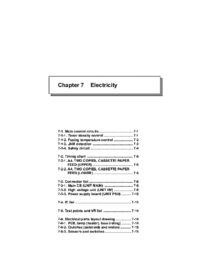
Chapter 7                     Electricity


7-1. Main control circuits ................................... 7-1
7-1-1. Toner density control .............................. 7-1
7-1-2. Fusing temperature control .................... 7-2
7-1-3. JAM detection .......................................... 7-3
7-1-4. Safety circuit ............................................ 7-4

7-2. Timing chart ................................................ 7-5
7-2-1. A4, TWO COPIES, CASSETTE PAPER
       FEED (UPPER) .......................................... 7-5
7-2-2. A4, TWO COPIES, CASSETTE PAPER
       FEED (LOWER) ......................................... 7-5

7-3. Connector list .............................................. 7-6
7-3-1. Main CB (UNIT MAIN) .............................. 7-6
7-3-2. High voltage unit (UNIT HV) .................... 7-9
7-3-3. Power supply board (UNIT PSU) .......... 7-12

7-4. IC list .......................................................... 7-13

7-5. Test points and VR list ............................. 7-14

7-6. Electrical parts layout drawing ................ 7-14
7-6-1. PCB, lamp (heater), fuse (rating) .......... 7-14
7-6-2. Clutches (solenoid) and motors ........... 7-15
7-6-3. Sensors and switches ........................... 7-15
                                                                                                                       Chapter 7 Electricity


    7-1. Main control circuits
    7-1-1. Toner density control
    1. Toner density detection
      The TNS signal detected by the toner sensor is relayed by the high voltage unit (UNIT HV) and connected to
      CN191-20 on the main CB (UNIT MAIN). After the TNS signal is changed to a partial voltage (TNS! signal) by the
      registance in the main CB, it is input into the IC121 (CPU) pin No. 77. The TNS! signal can be measured with the
      test point (TP103).
1   2. Toner motor drive control
      As the toner is consumed and the toner density becomes lighter than the optimum density, the TSM signal is
      output (HIGH -> LOW) from the IC121 No. 23 pin. The drive circuit in the high voltage PCB (UNIT HV) is acti-
      vated to rotate the toner motor (pulse motor) and supply the toner.
      Supply time: 3.5 sec.
1   3. Forced toner supply mode
      If the toner sensor detects a light density 1% less than the optimum density three times in succession, this unit
      will stop the copy operation, and forcibly supply toner. During this mode's operation, P25 will display (forcibly
      supplying toner).time: Max. 250 sec.
      When the toner density is recovered (6.5%), the stopped copy job will automatically resume. However, if the
      density is not recovered, P25 will blink (toner empty), and after 30 copies, the copy operation will stop.
    4. Initialization of developing unit
      When the unit's power is turned on in the unused state (when installed), P26 will light (developer not initialized),
      and the standby state will not be entered. This is so that the compensation voltage TNSC signal (analog voltage)
      applied on the toner sensor can be calculated beforehand so that the TNS signal will become the reference
      voltage in the new developer (unused) state. When the initialization operation (user mode C-51) is carried out,
      the detected compensation data will be saved in the main PCB's EEPROM (IC123). (Note: The developing unit
      must be initialized also when it has been replaced.)
             Initialization time: 6 min. (3 min. agitation + 3 min. reading & compensation data registration)
                       +5V         UNIT HV                                                        +24V


                    /TSM
                                                                                                                                   CN1251
                                                                                                     Q1251             TNM0         1
                                       CI1251B
                                                                 CI1251C

                                                                           Q1255                     Q1252
                                                                                                                                       Toner supply
                                                                                                                                       motor

                                                                                                     Q1253

         CN1261-5   TSMCLK                                                                                             TNM1        2
                                                                 CI1251D                                                   +24V
                                                                                                                                   3
                                                 CI1251A
                                                                                                                                   4
                                                                           Q1256                     Q1254                                     Toner sensor
                       GND24                                                                                                       5
                                                                                                                    TNS            6

                                                                                                                                   CN1261-4
                               UNIT MAIN                                                                                           CN191-19
                                                                            TP103                                   TNSC
                                                                                     TNS!
                    TSMCLK                                                                   77
         CN191-18
                                                      TP104
                                                                                                    IC121
         CN191-17    /TSM                                                            TNSC!
                                                                                              5


                                                                                    TSMCLK
                                                                                             45

                                                                                      TSM
                                                                                             23


             MODEL                           MANUAL           REVISED EDITION                DATA            PAGE                 METHOD
                                                                     7-1
                      1312 SERVICE HANDBOOK                           1                May.1999              7-1           REPLACEMENT
    Chapter 7 Electricity


    7-1-2 Fusing temperature control
      The surface temperature of the heat roller is detected with a thermistor, and is kept to a constant optimum tem-
      perature (188
◦ Jabse Service Manual Search 2026 ◦ Jabse Pravopis ◦ onTap.bg ◦ Other service manual resources online : Fixya ◦ eServiceinfo