Service Manuals, User Guides, Schematic Diagrams or docs for : Konica Minolta Copiers 7020 SERVICE 7020FVTE
<< Back | HomeMost service manuals and schematics are PDF files, so You will need Adobre Acrobat Reader to view : Acrobat Download Some of the files are DjVu format. Readers and resources available here : DjVu Resources
For the compressed files, most common are zip and rar. Please, extract files with Your favorite compression software ( WinZip, WinRAR ... ) before viewing. If a document has multiple parts, You should download all, before extracting.
Good luck. Repair on Your own risk. Make sure You know what You are doing.
Image preview - the first page of the document
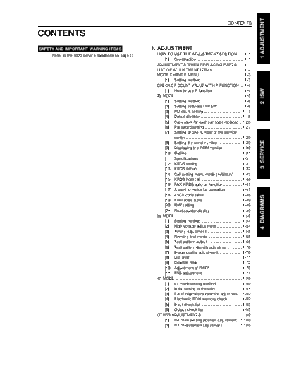
>> Download 7020FVTE documenatation <<
Text preview - extract from the document
                                                                                                                                       1 ADJUSTMENT
                                                                                                                 CONTENTS

CONTENTS
SAFETY AND IMPORTANT WARNING ITEMS .............       1. ADJUSTMENT
      Refer to the 7020 service handbook on page C-1    HOW TO USE THE ADJUSTMENT SECTION ...... 1-1
                                                            [1] Construction ........................................... 1-1
                                                        ADJUSTMENTS WHEN REPLACING PARTS ...... 1-1
                                                        LIST OF ADJUSTMENT ITEMS ............................. 1-2
                                                        MODE CHANGE MENU ......................................... 1-3
                                                            [1] Setting method ....................................... 1-3
                                                        CHECK OF COUNT VALUE WITH P FUNCTION .... 1-4


                                                                                                                                       2 ISW
                                                            [1] How to use P function ............................. 1-4
                                                        25 MODE ................................................................ 1-5
                                                            [1] Setting method ....................................... 1-6
                                                            [2] Setting software DIP SW ........................ 1-6
                                                            [3] PM count setting ................................... 1-17
                                                            [4] Data collection ...................................... 1-18
                                                            [5] Copy count for each part to be replaced .. 1-23
                                                            [6] Password setting .................................. 1-27
                                                            [7] Setting phone number of the service
                                                                 center .................................................... 1-29


                                                                                                                                       3 SERVICE
                                                            [8] Setting the serial number ...................... 1-29
                                                            [9] Displaying the ROM version ................. 1-30
                                                            [10] Outline .................................................. 1-31
                                                            [11] Specifications ....................................... 1-31
                                                            [12] KRDS setting ........................................ 1-31
                                                            [13] KRDS set up ......................................... 1-32
                                                            [14] Call setting menu mode (Arbitrary) ....... 1-43
                                                            [15] KRDS host call ..................................... 1-46
                                                            [16] FAX KRDS auto on function ................. 1-47
                                                            [17] A point to notice for operation ............... 1-47
                                                            [18] ASCII code table ................................... 1-48


                                                                                                                                       4 DIAGRAMS
                                                            [19] Error code table .................................... 1-49
                                                            [20] ISW setting ........................................... 1-49
                                                            [21] Root counter display ............................. 1-49
                                                        36 MODE .............................................................. 1-50
                                                            [1] Setting method ..................................... 1-54
                                                            [2] High voltage adjustment ....................... 1-54
                                                            [3] Timing adjustment ................................ 1-55
                                                            [4] Running test mode ............................... 1-65
                                                            [5] Test pattern output ............................... 1-66
                                                            [6] Test pattern density adjustment ........... 1-70
                                                            [7] Image quality adjustment ...................... 1-70
                                                            [8] List print ................................................ 1-71
                                                            [9] Counter clear ........................................ 1-72
                                                            [10] Adjustment of RADF ............................. 1-73
                                                            [11] FNS adjustment .................................... 1-77
                                                        47 MODE .............................................................. 1-90
                                                            [1] 47 mode setting method ....................... 1-90
                                                            [2] Initial setting in the field ........................ 1-91
                                                            [3] RADF original size detection adjustment ... 1-92
                                                            [4] Electronic RDH memory check ............. 1-92
                                                            [5] Input check list ...................................... 1-93
                                                            [6] Output check list ................................... 1-95
                                                        OTHER ADJUSTMENTS ................................... 1-100
                                                            [1] RADF mounting position adjustment .. 1-100
                                                            [2] RADF distortion adjustment ................ 1-100
1 ADJUSTMENT

               CONTENTS


                       [3]     RADF skew adjustment ...................... 1-101
                       [4]     DB-409 paper-incline adjustment ....... 1-101
                       [5]     DB-409 tray tilt adjustment ................. 1-102
               ISW
                 ISW ......................................................................... 2-1
                     [1] Description of the ISW ............................ 2-1
                     [2] Operating method ................................... 2-1
2 ISW


               SERVICE
                 SERVICE SCHEDULE ........................................... 3-1
                    [1] Service schedule .................................... 3-1
                    [2] Maintenance items ................................. 3-2
                    [3] Periodic check items (main body) ........... 3-5
                    [4] Periodic check items (options) ................ 3-7
                    [5] List of actual durable counters for
                         replacement parts ................................... 3-8
                 COPY MATERIALS ................................................ 3-9
                    [1] PM parts kit (100,000 copies/kit) ............ 3-9
3 SERVICE


                    [2] Consumables (Single unit supply) .......... 3-9
                 SERVICE MATERIALS LIST ................................ 3-10
                    [1] Maintenance kit composition ................ 3-10
                 SPECIAL TOOLS LIST ........................................ 3-11

               DIAGRAMS
                 7020 ELECTRICAL PARTS LAYOUT DRAWING .. 4-1
                     [1] Switches and sensors ............................. 4-1
                     [2] Loads ...................................................... 4-4
                     [3] PCBs and others .................................... 4-7
                 DF-314 ELECTRICAL PARTS LAYOUT DRAWING ... 4-9
4 DIAGRAM


                 FS-107 ELECTRICAL PARTS LAYOUT DRAWING .. 4-10
                 DB-209 ELECTRICAL PARTS LAYOUT DRAWING .. 4-12
                 DB-409 ELECTRICAL PARTS LAYOUT DRAWING .. 4-14
                 7020 CONNECTOR LAYOUT DRAWING ........... 4-15
                 DF-314 CONNECTOR LAYOUT DRAWING ....... 4-22
                 FS-107 CONNECTOR LAYOUT DRAWING ........ 4-23
                 DB-209 CONNECTOR LAYOUT DRAWING ....... 4-25
                 DB-409 CONNECTOR LAYOUT DRAWING ....... 4-26
                 LIST OF JAM CODES .......................................... 4-27
                 LIST OF WARNING (ERROR) CODES ............... 4-30
                 7020 TIME CHART (A4, LIFE SIZE,
                 2 COPIES, FEED FROM TRAY 1) ....................... 4-42
                 7020ADU TIME CHART (A4, LIFE SIZE,
                 3 COPIES, FEED FROM TRAY 1) ....................... 4-43
                 DF-314 TIME CHART (A4, SINGLE SIDE ORIGINAL,
                 3 SHEETS) ............................................................... 4-44
                 DF-314 TIME CHART (A4, DOUBLE SIDE
                 ORIGINALS, 2 SHEETS) ...................................... 4-45
                 FS-107 TIME CHART (A4, SORT MODE,
                 2 SHEETS/SET, 2 SETS) .................................... 4-46
                 FS-107 TIME CHART (A4, STAPLE MODE,
                 2 SHEETS, 1 POSITION) ..................................... 4-47
                 DB-209/DB409 TIME CHART (A4, LIFE SIZE,
                 3 COPIES, FEED FROM TRAY 1) ....................... 4-48
◦ Jabse Service Manual Search 2026 ◦ Jabse Pravopis ◦ onTap.bg ◦ Other service manual resources online : Fixya ◦ eServiceinfo