Service Manuals, User Guides, Schematic Diagrams or docs for : Konica Minolta Copiers 7020 SERVICE 7020TC0E
<< Back | HomeMost service manuals and schematics are PDF files, so You will need Adobre Acrobat Reader to view : Acrobat Download Some of the files are DjVu format. Readers and resources available here : DjVu Resources
For the compressed files, most common are zip and rar. Please, extract files with Your favorite compression software ( WinZip, WinRAR ... ) before viewing. If a document has multiple parts, You should download all, before extracting.
Good luck. Repair on Your own risk. Make sure You know what You are doing.
Image preview - the first page of the document
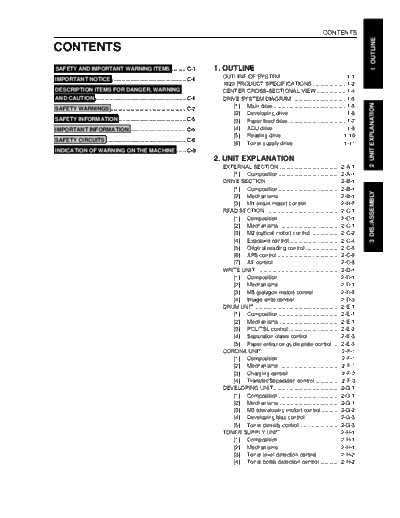
>> Download 7020TC0E documenatation <<
Text preview - extract from the document
CONTENTS
1 OUTLINE
CONTENTS
SAFETY AND IMPORTANT WARNING ITEMS ......... C-1 1. OUTLINE
OUTLINE OF SYSTEM .......................................... 1-1
IMPORTANT NOTICE ................................................ C-1
7020 PRODUCT SPECIFICATIONS ...................... 1-2
DESCRIPTION ITEMS FOR DANGER, WARNING CENTER CROSS-SECTIONAL VIEW ................... 1-4
AND CAUTION ........................................................... C-1 DRIVE SYSTEM DIAGRAM ................................... 1-5
2 UNIT EXPLANATION
SAFETY WARNINGS ................................................. C-2 [1] Main drive ............................................... 1-5
[2] Developing drive ..................................... 1-6
SAFETY INFORMATION ............................................ C-5 [3] Paper feed drive ..................................... 1-7
IMPORTANT INFORMATION .................................... C-5 [4] ADU drive ............................................... 1-9
[5] Reading drive ....................................... 1-10
SAFETY CIRCUITS .................................................... C-6
[6] Toner supply drive ................................ 1-11
INDICATION OF WARNING ON THE MACHINE ...... C-8
2. UNIT EXPLANATION
EXTERNAL SECTION ....................................... 2-A-1
[1] Composition ........................................ 2-A-1
DRIVE SECTION ............................................... 2-B-1
[1] Composition ........................................ 2-B-1
3 DIS./ASSEMBLY
[2] Mechanisms ....................................... 2-B-1
[3] M1 (main motor) control ..................... 2-B-2
READ SECTION ................................................ 2-C-1
[1] Composition ........................................ 2-C-1
[2] Mechanisms ....................................... 2-C-1
[3] M2 (optical motor) control ................... 2-C-2
[4] Exposure control ................................. 2-C-4
[5] Original reading control ...................... 2-C-5
[6] APS control ......................................... 2-C-6
[7] AE control ........................................... 2-C-8
WRITE UNIT ...................................................... 2-D-1
[1] Composition ........................................ 2-D-1
[2] Mechanisms ....................................... 2-D-1
[3] M5 (polygon motor) control ................. 2-D-2
[4] Image write control ............................. 2-D-3
DRUM UNIT ....................................................... 2-E-1
[1] Composition ........................................ 2-E-1
[2] Mechanisms ....................................... 2-E-1
[3] PCL/TSL control ................................. 2-E-2
[4] Separation claws control .................... 2-E-3
[5] Paper entrance guide plate control ..... 2-E-3
CORONA UNIT .................................................. 2-F-1
[1] Composition ........................................ 2-F-1
[2] Mechanisms ....................................... 2-F-1
[3] Charging control ................................. 2-F-2
[4] Transfer/Separation control ................ 2-F-3
DEVELOPING UNIT ........................................... 2-G-1
[1] Composition ........................................ 2-G-1
[2] Mechanisms ....................................... 2-G-1
[3] M3 (developing motor) control ............ 2-G-2
[4] Developing bias control ...................... 2-G-3
[5] Toner density control .......................... 2-G-3
TONER SUPPLY UNIT ...................................... 2-H-1
[1] Composition ........................................ 2-H-1
[2] Mechanisms ....................................... 2-H-1
[3] Toner level detection control .............. 2-H-2
[4] Toner bottle detection control ............. 2-H-2
CONTENTS
1 OUTLINE
CLEANING/TONER RECYCLE UNIT .................. 2-I-1 DRUM UNIT ....................................................... 3-E-1
[1] Composition .......................................... 2-I-1 [1] Removing and Reinstalling the
[2] Mechanisms ......................................... 2-I-1 drum unit ............................................. 3-E-1
PAPER FEED UNIT ............................................ 2-J-1 [2] Removing and Reinstalling the drum .. 3-E-1
2 [1] Composition ......................................... 2-J-1
[2] Mechanisms ........................................ 2-J-1
[3] Removing and Reinstalling the
separation claw ................................... 3-E-3
2 UNIT EXPLANATION
[3] Paper feed control ............................... 2-J-2 CORONA UNIT SECTION ................................. 3-F-1
[4] Paper up down control ......................... 2-J-3 [1] Removing and Reinstalling the
[5] Paper size detection control ................ 2-J-4 charging corona unit ........................... 3-F-1
[6] No paper detection control .................. 2-J-6 [2] Removing and Reinstalling the charge
[7] Control of paper-level detection ........... 2-J-6 control plate ........................................ 3-F-1
FIXING UNIT ...................................................... 2-K-1 [3] Replacing the charging wire ............... 3-F-2
[1] Composition ........................................ 2-K-1 [4] Removing and Reinstalling the
[2] Mechanisms ....................................... 2-K-1 transfer and separation corona unit .... 3-F-2
[3] Fixing temperature control .................. 2-K-2 [5] Replacing the transfer and separation
[4] SD4 (cleaning web SD) control .......... 2-K-4 wires ................................................... 3-F-3
ADU/PAPER EXIT SECTION .............................. 2-L-1 DEVELOPING UNIT ........................................... 3-G-1
3 DIS./ASSEMBLY
[1] Composition ......................................... 2-L-1 [1] Screws that must not be removed ...... 3-G-1
[2] Mechanisms ........................................ 2-L-2 [2] Removing and Reinstalling the
[3] Paper exit/ADU conveyance developing unit ................................... 3-G-1
switching control .................................. 2-L-2 [3] Replacing the developer ..................... 3-G-2
[4] ADU conveyance control ..................... 2-L-3 TONER SUPPLY UNIT ...................................... 3-H-1
OTHER CONTROLS .......................................... 2-M-1 [1] Removing and Reinstalling the toner
[1] Parts energized when the main power bottle ................................................... 3-H-1
switch is OFF ...................................... 2-M-1 [2] Removing and Reinstalling the toner
[2] Components operated by power supply unit .......................................... 3-H-1
switches SW1 and SW2 ..................... 2-M-1 CLEANING/TONER RECYCLING UNIT .............. 3-I-1
[3] Cooling fan control .............................. 2-M-2 [1] Removing and Reinstalling the
[4] Operation unit control ......................... 2-M-3 cleaning blade ...................................... 3-I-1
[5] Counter control ................................... 2-M-5 PAPER FEED UNIT ............................................ 3-J-1
[6] Option control ..................................... 2-M-6 [1] Replacing the by-pass pickup
roller/by-pass conveyance roller .......... 3-J-1
3. DISASSEMBLY / ASSEMBLY [2] Replacing the by-pass reversal roller .. 3-J-2
EXTERNAL SECTION ....................................... 3-A-1 [3] Replacing the feed rubber and the
[1] Replacing the ozone filter ................... 3-A-1 double feed prevention upper rubber
DRIVE SECTION ............................................... 3-B-1 (upper tray) .......................................... 3-J-2
[1] Removing and reinstalling the motor [4] Replacing the double feed prevention
units (main, paper feed, developing) .. 3-B-1 lower rubber (upper tray) ..................... 3-J-3
[2] Replacing the registration clutch ........ 3-B-2 [5] Replacing the feed rubber and double
[3] Replacing the loop clutch ................... 3-B-3 feed prevention upper rubber (lower tray) . 3-J-4
READ SECTION ................................................ 3-C-1 [6] Replacing the double feed prevention
[1] Screws that must not be removed ...... 3-C-1 lower rubber (lower tray) ...................... 3-J-5
[2] Removing the original glass ............... 3-C-1 [7] Replacing the registration rollers
[3] Removing and Reinstalling the CCD unit .. 3-C-2 1 and 2 ................................................. 3-J-6
[4] Replacing the exposure lamp ............. 3-C-3 FIXING UNIT ...................................................... 3-K-1
[5] Removing and Reinstalling the [1] Removing and Reinstalling the
exposure unit ...................................... 3-C-4 fixing unit ............................................ 3-K-1
[6] Removing and Reinstalling the [2] Replacing the fixing heater lamps
optics drive motor ............................... 3-C-5 (main lamp and sub lamp) .................. 3-K-1
[7] Removing the optics wire ................... 3-C-5 [3] Removing and Reinstalling the fixing
[8] Installing the optics wire ..................... 3-C-6 claw .................................................... 3-K-2
WRITE UNIT ...................................................... 3-D-1 [4] Replacing the fixing web/Fixing cleaning
[1] Removing and Reinstalling the write unit .. 3-D-1 roller .................................................... 3-K-3
CONTENTS
1 OUTLINE
[5]
Removing and Reinstalling the fixing
heat roller/fixing pressure roller .......... 3-K-4
[6] Removing and Reinstalling the fixing
temperature sensors ........................... 3-K-5
[7] Removing and Reinstalling the ther-
mostat ................................................. 3-K-5
2 UNIT EXPLANATION
ADU/PAPER EXIT SECTION .............................. 3-L-1
[1] Removing and Reinstalling the exit
sensor unit ........................................... 3-L-1
3 DIS./ASSEMBLY
◦ Jabse Service Manual Search 2026 ◦ Jabse Pravopis ◦ onTap.bg ◦ Other service manual resources online : Fixya ◦ eServiceinfo