Service Manuals, User Guides, Schematic Diagrams or docs for : LG Microwave Oven ms-194a 3828W5~5
<< Back | HomeMost service manuals and schematics are PDF files, so You will need Adobre Acrobat Reader to view : Acrobat Download Some of the files are DjVu format. Readers and resources available here : DjVu Resources
For the compressed files, most common are zip and rar. Please, extract files with Your favorite compression software ( WinZip, WinRAR ... ) before viewing. If a document has multiple parts, You should download all, before extracting.
Good luck. Repair on Your own risk. Make sure You know what You are doing.
Image preview - the first page of the document
>> Download 3828W5~5 documenatation <<
Text preview - extract from the document
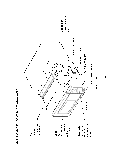
4-1. Construction of microwave oven


    Cavity
    Cabinet locking
    in microwave
    and holding
    food.


    Door
    Gate coming in
    and out food.                                                                      Magnetron
    It has window                                                                      Inject microwave
    and seal                                                                           to oven.
    structure
                                                                   OVEN CAVITY PARTS

    Controller                                                 INTERIOR PARTS
    Control and
    supervise                                           BASE PLATE PARTS
                      DOOR PARTS
    operating state
    of oven.
                                          LATCH BOARD PARTS

                              CONTROL PANEL PARTS


                                               - 15 -
4-2. How does the microwave oven operate?
After plugging your oven into a standard household socket, press start button or turn the timer. And then switches
(primary, secondary, timer) close the circuit.
Eventually the input power will be applied to turntable motor, timer motor, fan motor, oven lamp and high voltage transformer.
A high voltage of 2,100 volts AC is generated in the second winging of H.V.Transformer. And the voltage is doubled by
H.V.Capacitor & H.V.Diode. The 4Kv DC voltage is applied to filament of magnetron, then magnetron start to produce microwave.
This microwave is injected to cavity.


                                                                - 16 -
4-3. WARNING - High voltage circuit ( 4,000 volt )

                                          * The half-wave voltage doubler circuit consists of the secondary winding of
                                            the high voltage transformer, H.V. diode (rectifier), and H.V. capacitor. The
   INPUT           +   -                    H.V. diode allows alternating current (AC) to flow in one direction only and
           +                                rectifies it to pulsating direct current (DC).
                                            The H.V. capacitor is able to store energy on one half of the AC cycle and
                                            release it on the other half cycle.
               SENONDARY
               WINDING AT                 * During the first half cycle of operation, the secondary winding of the
                  2000V
                                            transformer supplies 2000 Volts to the capacitor current flows through the


                            MAGNETRON
                                            diode and returns to the transformer for a complete circuit. This half-cycle
           -                                of AC charges the capacitor to approximately 2000 Volts.


                   +   -
   INPUT
                                          * During the second half cycle of operation, the current flows in the opposite
           -
                                            direction, again supplies 2000 Volts to the circuit.

                                          * This permits the capacitor to discharge its 2000 Volts on top of the 2000
               SECONDARY                    Volts generated by the secondary winding, creating an approximate total
               WINDING AT
                  2000V                     voltage of negative 4000 Volts D.C.
                              MAGNETRON


                                            The negative 4000 Volts DC causes the magnetron to conduct current
           +                                and, to oscillate at 2450 MHz.
                                            The first half cycle and the second half cycle become one complete cycle,
                                            repeated input power frequency times per second .


                                                    - 17 -
4-4. Microwave generation system_Magnetron (1/2)

        GASKET                             ANTENNA (OUTPUT)
FILAMENT (CATHODE)                      MAGNET (MAGNETIC CIRCUIT)


          ANODE


  MAGNET (FERRITE)

                                         VANE

                                            FILAMENT TERMINALS


                                          FEED THROUGH CAPACITOR
      FILTER CASE
                     FILTER


                                             * The magnetron is the energy source for the microwave oven.
                              ANTENNA          The magnetron is a vacuum tube of special construction.
          ELECTRONS              CATHODE       It is basically a diode with addition of a magnetic field.
                                               It consists of a small, coiled heating element (filament) made of tungsten
                                               which readily emits electrons when heated.
                                               This element serves as the cathode (negative element) within the tube.
                                               The anode (positive element of the tube) consists of a thick walled copper
                                               cylinder with vertical vanes extending inward which surround but do not
                                               touch the cathode.
                                               To complete the magnetron, and make it operate distinctly different from
             ANODE                             other vacuum tubes, two permanent magnets are mounted over each end
                                               of the tube.


                                                         - 18 -
4-4. Microwave generation system_Magnetron (2/2)
                                                    * In order to create an electron flow from cathode to anode, the cathode must
                                                      be heated and a potential difference must exist between the two.
                                 2,450 MHz.
            ANTENNA                                   This is accomplished by heating the cathode with 3, 4 to 3,5 V AC. ( from the
                                                      filament winding of the high voltage transformer) and applying a negative
                                                      4000 V DC (from the voltage doubler circuit) to the cathode.
    ELECTRONS                        CATHODE
                                                    * Originally the electrons would travel in a straight line from the cathode to the
                                                      anode. However, with the addition of a permanent magnet surrounding the
                                                      anode creating a magnetic field, the electrons travel an orbital path between
                                                      the cathode and anode. As the electrons approach the anode, their orbital
                                                      path takes them past small resonant cavities that are part of the anode.
                                                      The passing notion of the electrons induces electron current to oscillate in the
                                   PERMANENT
    ANODE
                                   MAGNET             resonant cavities at the very high frequency or 2,450 MHz.
                                                      This RF (Radio frequency) energy is then transferred to the antenna.


TESTING MAGNETRON TUBE

* Disconnect power, remove the wrapper, and discharge the capacitor.

* Remove the two leads from the magnetron terminals.

* Connect the ohmmeter between one terminal of the magnetron and the outer case of the magnetron. If the ohmmeter reads
  infinity, go to below. If the ohmmeter reads less than infinity, the magnetron is shorted.

* Connect an ohmmeter across the terminals of the magnetron. The ohmmeter should read less than one ohm              f the
  ohmmeter reads over one ohm or infinity, the tube is defective.


                                                                - 19 -
◦ Jabse Service Manual Search 2026 ◦ Jabse Pravopis ◦ onTap.bg ◦ Other service manual resources online : Fixya ◦ eServiceinfo