Service Manuals, User Guides, Schematic Diagrams or docs for : LG Audio ffh-315 f313adjust
<< Back | HomeMost service manuals and schematics are PDF files, so You will need Adobre Acrobat Reader to view : Acrobat Download Some of the files are DjVu format. Readers and resources available here : DjVu Resources
For the compressed files, most common are zip and rar. Please, extract files with Your favorite compression software ( WinZip, WinRAR ... ) before viewing. If a document has multiple parts, You should download all, before extracting.
Good luck. Repair on Your own risk. Make sure You know what You are doing.
Image preview - the first page of the document

>> Download f313adjust documenatation <<
Text preview - extract from the document
                                       ADJUSTMENTS
This set has been aligned at the factory and normally will not require further adjustment. As a result, it is not
recommended that any attempt is made to modificate any circuit. If any parts are replaced or if anyone tampers
with the adjustment, realignment may be necessary.


IMPORTANT
1. Check Power-source voltage.
2. Set the function switch to band being aligned.
3. Turn volume control to minimum unless otherwise noted.
4. Connect low side of signal source and output indicator to chassis ground unless otherwise specified.
5. Keep the signal input as low as possible to avoid AGC and AC action.


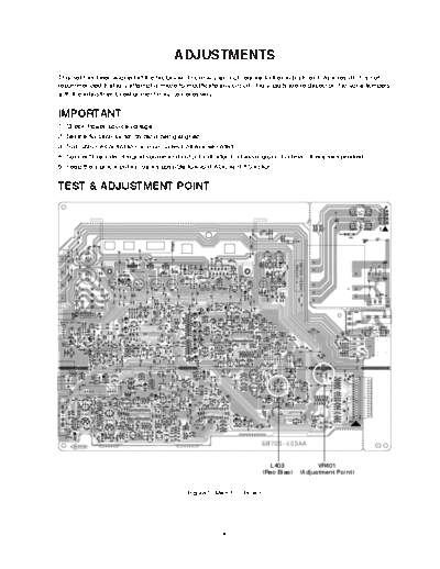
TEST & ADJUSTMENT POINT


                                                                          L403             VR401
                                                                        (Rec Bias)   (Adjustment Point)


                                            Figure 1. Main P.C. Board


                                                      -8-
TAPE DECK ADJUSTMENT
1. AZIMUTH ADJUSTMENT

     Deck Mode                      Test Tape                     Test Point              Adjustment                Adjust for
   A Deck Playback                   MTT-114                      Speaker Out            Azimuth Screw              Maximum
   B Deck Playback                   MTT-114                      Speaker Out            Azimuth Screw              Maximum


                                                                            Electronic           Dual-trace
                                                                            Voltmeter            synchroscope

                      Head
                                        Playback Mode
                                                           Speaker Out
                                                   L out
                            L ch                                                                 CH1 CH2

              Test Tape                     Unit
              MTT-114      R ch                                                                          GND


                                                   R out


                                     Figure 2. Azimuth Adjustment Connection Diagram


2. MOTOR SPEED ADJUSTMENT

    Deck Mode              Test Tape                Test Point              Adjustment          Adjust for           Remark
   Normal Speed             MTT-111                Speaker Out                 VR401           3kHz
◦ Jabse Service Manual Search 2024 ◦ Jabse Pravopis ◦ onTap.bg ◦ Other service manual resources online : Fixya ◦ eServiceinfo