Service Manuals, User Guides, Schematic Diagrams or docs for : LG Air Conditioner lwb762cl AR3757~4

<< Back | Home

Most service manuals and schematics are PDF files, so You will need Adobre Acrobat Reader to view : Acrobat Download Some of the files are DjVu format. Readers and resources available here : DjVu Resources
For the compressed files, most common are zip and rar. Please, extract files with Your favorite compression software ( WinZip, WinRAR ... ) before viewing. If a document has multiple parts, You should download all, before extracting.
Good luck. Repair on Your own risk. Make sure You know what You are doing.


Image preview - the first page of the document
AR3757~4


>> Download AR3757~4 documenatation <<

Text preview - extract from the document
4. TROUBLESHOOTING GUIDE
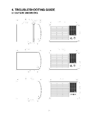
4.1 OUTSIDE DIMENSIONS


            487mm(19 3/16 ")
                      140.5mm(5 1/2 ")            510mm(20 1/16 ")
                 1
         28.5mm(1 /8")


                                                                                                                                                               353mm(13 7/8 ")
                                                                                                              MODE
                                                                                        REGULAR                       ECONOMY

                                                                                                                                     OFF CO O
                                                                          9                    1                              F AN           L
                                                                                                                     HIGH                         HIGH
                                                                     8                                  2

                                                                                                                    LOW                                  LOW
                                                                     7                                  3


                                                                                                        LER
                                                                          6                    4


                                                                                                   OO
                                                                                                    C
                                                                                    5
                                                                                                        BEFORE RESTARTING
                                                                         THERMOSTAT                     WAIT THREE MINUTES   OPERATION


                  218mm(8 15/26")


            487mm(19 3/16 ")                      510mm(20 1/16 ")


                                                                                                                                                               353mm(13 7/8 ")
                                                                                                                              F AN
                                                                                                                                     0   CO O
                                                                                                                                             L
                                                                          9                    1
                                                                                                                     HIGH                        HIGH
                                                                     8                              2

                                                                                                                    LOW                                 LOW
                                                                     7                              3


                                                                                                        LER
                                                                          6                    4


                                                                                                   OO
                                                                                                    C
                                                                                    5
                                                                                                    BEFORE RESTARTING
                                                                         THERMOSTAT                 WAIT THREE MINUTES       OPERATION


                  218mm(8 15/26")


             487mm(19 3/16 ")                     510mm(20 1/16 ")
                                                                                                                                                                 353mm(13 7/8 ")


                                                                               MODE                SLEEP
                                                                                                                                         AUTO RESTART

                                                                              FAN       COOL            ON                               ON        OFF


                                                                              FAN SPEED                      TEMP                         POWER


                   218mm(8 15/26")


                                         --20--
4.2 PIPING SYSTEM

   CONDENSER COIL

                    FAN
                                                                                                CAPILLARY TUBE
                MOTOR

                                                                                                COMPRESSOR


                                                                                                BLOWER


                                                                                                EVAPORATOR COIL


  Discharge the refrigerant system using a Freon TM Recovery
  System. If there is no valve to attach the recovery system,                             : REFRIGERANT FLOW
  install one (such as a WATCO A-1) before venting the FreonTM.
  Leave the valve in place after servicing the system. Do not
  vent FreonTM into the atmosphere.


The following is a brief description of the important components and their function in what is called the refrigeration
system. Reference should made to figure 31 to follow the refrigerating cycle and the flow of the refrigerant in the
cooling cycle.


                                                ROOM AIR CONITIONER
                                                CYCLE OF REFRIGERATION
            EVAPORATOR COILS                                                          CONDENSER COILS
                                                                            VAPOR INLET
                                                  SUCTION LINE
                              COMPLETE LIQUID                                                              HOT
                                                  COOL LOW PRESSURE VAPOR
                              BOIL OFF POINT                                                               DISCHARGED
       COOLED                                                                                              AIR
       AIR
                                ROOM AIR HEAT LOAD


                                                                      OUTSIDE COOLING
                                                                      AIR FOR REFRIGERANT
                                                                      PASS THROUGH
                                                     MOTOR


                                                 COMPRESSOR

                                                     OIL
                LIQUID
                PRESSURE                                                                  LIQUID OUTLET
                DROP
                                            (LIQUID REFRIGERANT)
                                                                                              HIGH PRESSURE VAPOR

                                         CAPILLARY TUBE                                       LIQUID REFRIGERANT
                                                                                              LOW PRESSURE VAPOR

                                                      Figure 31

                                                           --21--
4.3 TROUBLESHOOTING GUIDE
    In general, possible trouble is classified in two kinds.
    The one is called Starting Failure which is caused from an electrical defect. The other is Ineffective Air
    Conditioning caused by a defect in the refrigeration circuit and improper application.

Unit runs but poor cooling is ineffective.

                                               Ineffective Cooling


  Check of cold air circulation            Check of outdoor coil                    Check heat load
  for smooth flow.                         (heat exchanger) & fan                   increase.
                                           operation.


                                                                                    Clean condenser.
  Dirty indoor coil                        Check gas leakage.
  (Heat exchanger)


                                                                                    Not on separate circuit
                                           Repair gas leak.
  Malfunction of fan


                                                                                    Check inside gas
  Clogged of air filter                    Replacement of unit if the               pressure.
                                           unit is beyond repair.


  Obstruction at air outlet
                                                                                    Adjusting of refrigerant
                                                                                    charge


  Remove obstruction.


                                                                                    Malfunction of compressor


  Check clogging in                                                                 Replacement of
  refrigeration circuit.                                                            compressor


                                          Satisfactory operation with
  Repair clogging in                      temperature difference of
  refrigeration circuit.                  inlet & outlet air ;
                                          44~50


◦ Jabse Service Manual Search 2024 ◦ Jabse PravopisonTap.bg ◦ Other service manual resources online : FixyaeServiceinfo