Service Manuals, User Guides, Schematic Diagrams or docs for : LG Car Audio TCC-6410 SPEC_&_ADJUSTMENTS
<< Back | HomeMost service manuals and schematics are PDF files, so You will need Adobre Acrobat Reader to view : Acrobat Download Some of the files are DjVu format. Readers and resources available here : DjVu Resources
For the compressed files, most common are zip and rar. Please, extract files with Your favorite compression software ( WinZip, WinRAR ... ) before viewing. If a document has multiple parts, You should download all, before extracting.
Good luck. Repair on Your own risk. Make sure You know what You are doing.
Image preview - the first page of the document
>> Download SPEC_&_ADJUSTMENTS documenatation <<
Text preview - extract from the document
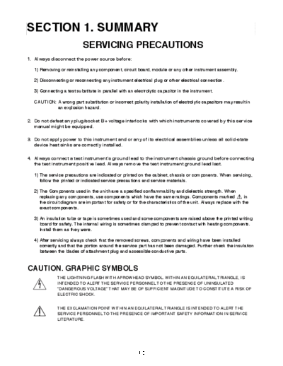
SECTION 1. SUMMARY
                            SERVICING PRECAUTIONS
1. Always disconnect the power source before:

   1) Removing or reinstalling any component, circuit board, module or any other instrument assembly.

   2) Disconnecting or reconnecting any instrument electrical plug or other electrical connection.

   3) Connecting a test substitute in parallel with an electrolytic capacitor in the instrument.

   CAUTION: A wrong part substitution or incorrect polarity installation of electrolytic capacitors may result in
            an explosion hazard.

2. Do not defeat any plug/socket B+ voltage interlocks with which instruments covered by this service
   manual might be equipped.

3. Do not apply power to this instrument and or any of its electrical assemblies unless all solid-state
   device heat sinks are correctly installed.

4. Always connect a test instrument's ground lead to the instrument chassis ground before connecting
   the test instrument positive lead. Always remove the test instrument ground lead last.

   1) The service precautions are indicated or printed on the cabinet, chassis or components. When servicing,
      follow the printed or indicated service precautions and service materials.

   2) The Components used in the unit have a specified conflammability and dielectric strength. When
      replacing any components, use components which have the same ratings. Components marked                   in
      the circuit diagram are important for safety or for the characteristics of the unit. Always replace with the
      exact components.

   3) An insulation tube or tape is sometimes used and some components are raised above the printed writing
      board for safety. The internal wiring is sometimes clamped to prevent contact with heating components.
      Install them as they were.

   4) After servicing always check that the removed screws, components and wiring have been installed
      correctly and that the portion around the service part has not been damaged. Further check the insulation
      between the blades of attachment plug and accessible conductive parts.


CAUTION. GRAPHIC SYMBOLS
               THE LIGHTNING FLASH WITH APROWHEAD SYMBOL. WITHIN AN EQUILATERAL TRIANGLE, IS
               INTENDED TO ALERT THE SERVICE PERSONNEL TO THE PRESENCE OF UNINSULATED
               "DANGEROUS VOLTAGE" THAT MAY BE OF SUFFICIENT MAGNITUDE TO CONSTITUTE A RISK OF
               ELECTRIC SHOCK.


               THE EXCLAMATION POINT WITHIN AN EQUILATERAL TRIANGLE IS INTENDED TO ALERT THE
               SERVICE PERSONNEL TO THE PRESENCE OF IMPORTANT SAFETY INFORMATION IN SERVICE
               LITERATURE.


                                                       - 1-2 -
                                 ESD PRECAUTIONS
Some semiconductor (solid state) devices can be damaged easily by static electricity. Such omponents
commonly are called Electrostatically Sensitive Devices (ESD). Examples of typical ESD devices are
integrated circuits and some field-effect transistors and semiconductor chip components. The following
techniques should be used to help reduce the incidence of component damage caused by static electricity.


1) Immediately before handling any semiconductor component or semiconductor-equipped assembly, drain
   off any electrostatic charge on your body by touching a known earth ground. Alternatively, obtain and
   wear a commercially available discharging wrist strap device, which should be removed for potential
   shock reasons prior to applying power to the unit under test.


2) After removing an electrical assembly equipped with ESD devices, place the assembly on a conductive
   surface such as aluminum foil, to prevent electrostatic charge buildup or exposure of the assembly.


3) Use only a grounded-tip soldering iron to solder or unsolder ESD devices.


4) Use only an anti-static solder removal device. Some solder removal devices not classified as "anti-static"
   can generate electrical charges sufficient to damage ESD devices.


5) Do not use freon-propelled chemicals. These can generate electrical charges sufficient to damage ESD
   devices.


6) Do not remove a replacement ESD device from its protective package until immediately before you are
   ready to install it. (Most replacement ESD devices are packaged with leads electrically shorted together
   by conductive foam, aluminum foil or comparable conductive material).


7) Immediately before removing the protective material from the leads of a replacement ESD device, touch
   the protective material to the chassis or circuit assembly into which the device will be installed.


  CAUTION: Be sure no power is applied to the chassis or circuit, and observe all other safety precautions.

8) Minimize bodily motions when handling unpackaged replacement ESD devices. (Otherwise harmless
   motion such as the brushing together of your clothes fabric or the lifting of your foot from a carpeted floor
   can generate static electricity sufficient to damage an ESD device).


                                                    - 1-3 -
                                                      SPECIFICATIONS
1. GENERAL
  Power requirements ..................................................................................................................... DC12V~15V
  Ground system ................................................................................................................................... Negative
  Dimensions(W x H x D) ...................................................................................................... 188 x 58 x 166mm
  Weight .............................................................................................................................................. Net: 1.3kg


2. RADIO SECTION
                                                   FM                                               AM(MW)                                    LW(Optional)
  Frequency range ................................. 65.0~74.0MHz(Optional),                         522~1,620kHz                              144~281kHz
                                                    87.5~108MHz                                     (Optional:530~1,710kHz/
                                                                                                              520~1,620kHz)
  Intermediate frequency ....................... 10.7MHz                                            450kHz                                    450kHz
  Usable sensitivity ................................ 10dB
◦ Jabse Service Manual Search 2026 ◦ Jabse Pravopis ◦ onTap.bg ◦ Other service manual resources online : Fixya ◦ eServiceinfo