Service Manuals, User Guides, Schematic Diagrams or docs for : LG LCD LG MF004A CHASSIS LL15A10 LCD TV lg_mf004a_chassis_ll15a10_lcd_tv_sm_430
<< Back | HomeMost service manuals and schematics are PDF files, so You will need Adobre Acrobat Reader to view : Acrobat Download Some of the files are DjVu format. Readers and resources available here : DjVu Resources
For the compressed files, most common are zip and rar. Please, extract files with Your favorite compression software ( WinZip, WinRAR ... ) before viewing. If a document has multiple parts, You should download all, before extracting.
Good luck. Repair on Your own risk. Make sure You know what You are doing.
Image preview - the first page of the document
>> Download lg_mf004a_chassis_ll15a10_lcd_tv_sm_430 documenatation <<
Text preview - extract from the document
website:http://biz.LGservice.com
e-mail:http://www.LGEservice.com/techsup.html
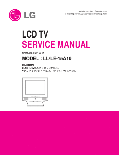
LCD TV
SERVICE MANUAL
CHASSIS : MF-004A
MODEL : LL/LE-15A10
CAUTION
BEFORE SERVICING THE CHASSIS,
READ THE SAFETY PRECAUTIONS IN THIS MANUAL.
CONTENTS
Contents .................................................................................................. 2
Safety Precautions ..................................................................................3
Servicing Precautions ............................................................................ 4
Description of Controls .......................................................................... 6
Adjustment Instruction ............................................................................9
Troubleshooting......................................................................................11
Exploded View ...................................................................................... 12
Exploded View Parts List .......................................................................13
Replacement Parts List ........................................................................ 14
SVC. Sheet .................................................................................................
-2-
SAFETY PRECAUTIONS
IMPORTANT SAFETY NOTICE
Many electrical and mechanical parts in this chassis have special safety-related characteristics. These parts are
identified by in the Schematic Diagram and Replacement Parts List.
It is essential that these special safety parts should be replaced with the same components as recommended in this
manual to prevent X-RADIATION, Shock, Fire, or other Hazards.
Do not modify the original design without permission of manufacturer.
General Guidance
always perform an AC leakage current check on the
An lsolation Transformer should always be used during exposed metallic parts of the cabinet, such as antennas,
the servicing of a receiver whose chassis is not isolated terminals, etc., to be sure the set is safe to operate without
from the AC power line. Use a transformer of adequate damage of electrical shock.
power rating as this protects the technician from
accidents resulting in personal injury from electrical Leakage Current Cold Check(Antenna Cold Check)
shocks. With the instrument AC plug removed from AC source,
connect an electrical jumper across the two AC plug
It will also protect the receiver and it's components from prongs. Place the AC switch in the on positioin, connect
being damaged by accidental shorts of the circuitary that one lead of ohm-meter to the AC plug prongs tied
may be inadvertently introduced during the service together and touch other ohm-meter lead in turn to each
operation. exposed metallic parts such as antenna terminals, phone
jacks, etc.
If any fuse (or Fusible Resistor) in this TV receiver is If the exposed metallic part has a return path to the
blown, replace it with the specified. chassis, the measured resistance should be between 1M
and 5.2M .
When replacing a high wattage resistor (Oxide Metal Film When the exposed metal has no return path to the chassis
Resistor, over 1W), keep the resistor 10mm away from the reading must be infinite.
PCB. An other abnormality exists that must be corrected before
the receiver is returned to the customer.
Keep wires away from high voltage or high temperature
parts. Leakage Current Hot Check (See below Figure)
Plug the AC cord directly into the AC outlet.
Due to high vacuum and large surface area of picture Do not use a line Isolation Transformer during this check.
tube, extreme care should be used in handling the Picture Connect 1.5K/10watt resistor in parallel with a 0.15uF
Tube. Do not lift the Picture tube by it's Neck. capacitor between a known good earth ground (Water
Pipe, Conduit, etc.) and the exposed metallic parts.
The source of X-RAY RADIATION in this TV receiver is Measure the AC voltage across the resistor using AC
the High Voltage Section and the Picture Tube. voltmeter with 1000 ohms/volt or more sensitivity.
For continued X-RAY RADIATION protection, the Reverse plug the AC cord into the AC outlet and repeat AC
replacement tube must be the same type tube as voltage measurements for each esposed metallic part. Any
specified in the Replacement Parts List. voltage measured must not exceed 0.75 volt RMS which is
corresponds to 0.5mA.
In case any measurement is out of the limits sepcified,
X-RAY Radiation there is possibility of shock hazard and the set must be
checked and repaired before it is returned to the
Warning: customer.
To determine the presence of high voltage, use an Leakage Current Hot Check circuit
accurate high impedance HV meter.
AC Volt-meter
Adjust brightness, color, contrast controls to minimum.
Measure the high voltage.
The meter reading should indicate
23.5 !1.5KV: 14-19 inch, 26!1.5KV: 19-21 inch,
Good Earth Ground
29.0!1.5KV: 25-29 inch, 30.0 !1.5KV: 32 inch such as WATER PIPE,
If the meter indication is out of tolerance, immediate To Instrument's 0.15uF CONDUIT etc.
service and correction is required to prevent the exposed
possibility of premature component failure. METALLIC PARTS
Before returning the receiver to the customer, 1.5 Kohm/10W
-3-
SERVICING PRECAUTIONS
CAUTION: Before servicing receivers covered by this service transistors and semicounductor "chip" components. The
manual and its supplements and addenda, read and follow following techniques should be used to help reduce the
the SAFETY PRECAUTIONS on page 3 of this publication. incidence of component damage caused by static by static
NOTE: If unforeseen circumstances create conflict between electricity.
the following servicing precautions and any of the safety 1 Immediately before handling any semiconductor
.
precautions on page 3 of this publication, always follow the component or semiconductor-equipped assembly, drain
safety precautions. Remember: Safety First. off any electostatic charge on your body by touching a
known earth ground. Alternatively, obtain and wear a
General Servicing Precautions commercially available discharging wrist strap device,
1 Always unplug the receiver AC power cord from the AC
. which should be removed to prevent potential shock
power source before; reasons prior to applying power to the unit under test.
a Removing or reinstalling any component, circuit board
. 2 After removing an electrical assembly equipped with ES
.
module or any other receiver assembly. devices, place the assembly on a conductive surface such
b Disconnecting or reconnecting any receiver electrical
. as aluminum foil, to prevent electrostatic charge buildup
plug or other electrical connection. or exposure of the assembly.
c Connecting a test substitute in parallel with an
. 3 Use only a grounded-tip soldering iron to solder or
.
electrolytic capacitor in the receiver. unsolder ES devices.
CAUTION: A wrong part substitution or incorrect 4 Use only an anti-static type solder removal device. Some
.
polarity installation of electrolytic capacitors may solder removal devices not classified as "anti-static" can
result in an explosion hazard. generate electrical charges sufficent to demage ES devices.
d Discharging the picture tube anode.
. 5 Do not use freon-propelled chemicals. These can generate
.
2 Test high voltage only by measuring it with an
. electrical charges sufficient to damage ES devices.
appropriate high voltage meter or other voltage 6 Do not remove a repalcement ES device from its protective
.
measuring device (DVM, FETVOM, etc) equipped with a package until immediately before you are ready to install
suitable high voltage probe. it. (Most replacement ES devices are packaged with leads
Do not test high voltage by "drawing an arc". electrically shorted together by conductive foam,
3 Discharge the picture tube anode only by (a) first
. aluminum foil or comparable conductive material).
connecting one end of an insulated clip lead to the 7 Immediately before removing the protective material from
.
degaussing or kine aquadag grounding system shield at the ieads of a replacement ES device, touch the protective
the point where the picture tube socket ground lead is material to the chassis or circuit assembly into which the
connected, and then (b) touch the other end of the device will be installed.
insulated clip lead to the picture tube anode button, using CAUTION:Be sure no power is applied to the chassis or
an insulating handle to avoid personal contact with high circuit, and observe all other safety precautions.
voltage. 8 Minimize bodily motions when handling unpackaged
.
4 Do not spray chemicals on or near this receiver or any of
. replacement ES devices. (Otherwise harmless motion such
its assemblies. as the bruching together of your clothes fabric or the
5 Unless specified otherwise in this service manual, clean
. lifting of your foot from a carpeted floor can generate
electrical contacts only by applying the following mixture static electricity sufficient to damage an ES device.)
to the contacts with a pipe cleaner, cotton-tipped stick or
comparable nonabrasive applicator; 10% (by volume) General Soldering Guidelines
Acetone and 90% (by volume) isopropyl alcohol (90%-99% 1 Use a grounded-tip, low-wattage soldering iron and
.
strength) appropriate tip size and shape that will maintan tip
CAUTION: This is a flammable mixture. temperature within the range or 500cF to 600cF .
Unless specified otherwise in this service manual, 2 Use an appropriate gauge of RMA resin-core solder
.
lubrication of contacts in not required. composed of 60 parts tin/40 parts lead.
6 Do not defeat any plug/socket B+ voltage interlocks with
. 3 Keep the soldering iron tip clean and well tinned.
.
which receivers covered by this service manual might be 4 Thorohly clean the surfaces to be soldered. Use a mall
.
equipped. wirebristle (0.5 inch, or 1.25cm) brush with a metal
7 Do not apply AC power to this instrument and/or any of
. handle.
its electrical assemblies unless all solid-state device heat Do not use freon-propelled spray-on cleaners.
sinks are correctly installed. 5 Use the following unsoldering technique
.
8 Always connect the test receiver ground lead to the
. a Allow the soldering iron tip to reach normal
.
receiver chassis ground before connecting the test receiver temperature.
positive lead. (500cF to 600cF)
Always remove the test receiver ground lead last. b Heat the component lead until the solder melts.
.
9 Use with this receiver only the test fixtures specified in this service
. c Quickly draw the melted solder with an anti-static,
.
manual. suction-type solder removal device or with solder braid.
CAUTION: Do not connect the test fixture ground strap to C A U T I O N : Work quickly to avoid overheating the
any heatsink in this receiver. circuiboard printed foil.
6 Use the following soldering technique.
.
Electrostatically Sensitive (ES) Devices a Allow the soldering iron tip to reach a normal
.
Some semiconductor (solid state) devices can be damaged temperature (500cF to 600cF)
easily by static electricity. Such components commonly are b First, hold the soldering iron tip and solder the strand
.
called Electrostatically Sensitive (ES) Devices. Examples of typical against the component lead until the solder melts.
ES devices are integrated circuits and some fieldeffect
-4-
c
. Qulckly move the soldering iron tip to the junction of joints of the two "original" leads. If they are not shiny,
the component lead and the printed circuit foil, and reheat them and if necessary, apply additional solder.
hold it there only until the solder flows onto and Fuse and Conventional Resistor
around both the component lead and the foil. Removal/Replacement
CAUTION: Work quickly to avoid overheating the 1 Clip each fuse or resistor lead at top of the circuit board
.
circuit board printed foil. hollow stake.
d. Closely inspect the solder area and remove any excess 2 Securely crimp the leads of replacement component
.
or splashed solder with a small wire-bristle brush. around notch at stake top.
3 Solder the connections.
.
IC Remove/Replacement CAUTION: Maintain original spacing between the replaced
Some chassis circuit boards have slotted holes (oblong) component and adjacent components and the circuit
through which the IC leads are inserted and then bent flat board to prevent excessive component temperatures.
against the circuit foil. When holes are the slotted type, the
following technique should be used to remove and replace Circuit Board Foil Repair
the IC. When working with boards using the familiar round Excessive heat applied to the copper foil of any printed
hole, use the standard technique as outlined in parapraphs 5 circuit board will weaken the adhesive that bonds the foil to
and 6 above. the circuit board causing the foil to separate from or "lift-off"
the board. The following guidelines and procedures should
Removal be followed whenever this condition is encountered.
1 Desolder and straighten each IC lead in one operation by
.
gently prying up on the lead with the soldering iron tip as At IC Connections
the solder melts. To repair a defective copper pattern at IC connections use
2 Draw away the melted solder with an anti-static suction-
. the following procedure to install a jumper wire on the
type solder removal device (or with solder braid) before copper pattern side of the circuit board. (Use this technique
removing the IC. only on IC connections).
Replacement
1 Carefully insert the replacement IC in the circuit boare.
. 1 Carefully remove the damaged copper pattern with a
.
2 Carefully bend each IC lead against the circuit foil pad and
. sharp knife. (Remove only as much copper as absolutely
solder it. necessary).
3 Clean the soldered areas with a small wire-bristle brush.
. 2 carefully scratch away the solder resist and acrylic coating
.
(It is not necessary to reapply acrylic coating to the areas). (if used) from the end of the remaining copper pattern.
3 Bend a small "U" in one end of a small gauge jumper wire
.
"Small-Signal" Discrete Transistor and carefully crimp it around the IC pin. Solder the IC
Removal/Replacement connection.
1 Remove the defective transistor by clipping its leads as
. 4 Route the jumper wire along the path of the out-away
.
close as possible to the component body. copper pattern and let it overlap the previously scraped
2 Bend into a "U" shape the end of each of three leads
. end of the good copper pattern. Solder the overlapped
remaining on the circuit board. area and clip off any excess jumper wire.
3 Bend into a "U" shape the replacement transistor leads.
.
4 Connect the replacement transistor leads to the
. At Other Connections
corresponding leads extending from the circuit board and Use the following technique to repair the defective copper
crimp the "U" with long nose pliers to insure metal to pattern at connections other than IC Pins. This technique
metal contact then solder each connection. involoves the installation of a jumper wire on the component
side of the circuit board.
Power Output, Transistor Device
Removal/Replacement 1 Remove the defective copper pattern with a sharp knife.
.
1 Heat and remove all solder from around the transistor
. Remove at least 1/4 inch of copper, to ensure that a
leads. hazardous condition will not exist if the jumper wire
2 Remove the heatsink mounting screw (if so equipped).
. opens.
3 Carefully remove the transistor from the heat sink of the
. 2 Trace along the copper pattern from both sides of the
.
circuit board. pattern break and locate the nearest component that is
4 Insert new transistor in the circuit board.
. directly connected to the affected copper pattern.
5 Solder each transistor lead, and clip off excess lead.
. 3 Connect insulated 20-gauge jumper wire from the lead of
.
6 Replace heatsink.
. the nearest component on one side of the pattern break to
the lead of the nearest component on the other side.
Diode Removal/Replacement Carefully crimp and solder the connections.
1 Remove defective diode by clipping its leads as close as
. CAUTION: Be sure the insulated jumper wire is dressed so
possible to diode body. the it does not touch components or sharp edges.
2 Bend the two remaining leads perpendicula y to the circuit
.
board.
3 Observing diode polarity, wrap each lead of the new diode
.
around the corresponding lead on the circuit board.
4 Securely crimp each connection and solder it.
.
5 Inspect (on the circuit board copper side) the solder
.
-5-
DESCRIPTION OF CONTROLS
All the functions can be controlled with the remote control handset.
Some functions can also be adjusted with the buttons on the front
panel of the set.
Remote control handset
POWER MUTE
Before you use the remote control handset, please install the bat-
1 teries. See the next page.
1 2 3 1. POWER
switches the set on from standby or off to standby.
2 4 5 6
2. NUMBER BUTTONS
7 8 9 switches the set on from standby or directly select a number.
MENU TV/AV/PC
3 0 3. MENU
SLEEP
selects a menu.
PR
4. D / E (Programme Up/Down)
4 VOL
OK
VOL selects a programme or a menu item.
switches the set on from standby.
Q.VIEW PR LIST F / G (Volume Up/Down)
5 adjusts the volume.
adjusts menu settings.
TEXT MIX INDEX OK
i
TIME REVEAL MODE
accepts your selection or displays the current mode.
M
SIZE HOLD UPDATE 5. Q.VIEW
returns to the previously viewed programme.
I/II PSM
6
6. I/II
7 selects the language during dual language broadcast.
selects the sound output (option).
7. PSM (Picture Status Memory)
recalls your preferred picture setting.
-6-
8. MUTE
switches the sound on or off.
9. TV/AV/PC
selects TV, AV or PC monitor mode.
clears the menu from the screen.
switches the set on from standby.
POWER MUTE
10. SLEEP 8
sets the sleep timer.
1 2 3
11. LIST
displays the programme table. 4 5 6
12. TELETEXT BUTTONS (option) 7 8 9
These buttons are used for teletext. MENU TV/AV/PC
For further details, see the `Teletext' section. 0 9
SLEEP
Note : In teletext mode, the SLEEP, LIST and Q.VIEW buttons are 10
PR
used for teletext function.
VOL VOL
OK
Battery installation Q.VIEW PR LIST
11
The remote control handset is powered by two AAA type batteries.
TEXT MIX INDEX
To load the batteries, turn the remote control handset over and i 12
open the battery compartment. Install two batteries as indicated by TIME REVEAL MODE
the polarity symbols ( + and - ) marked inside the compartment. M
SIZE HOLD UPDATE
I/II PSM
Note : To avoid damage from possible battery leakage, remove the
batteries if you do not plan to use the remote control handset for an
extended period of time.
-7-
Front panel
You can use the front panel buttons softly touching them instead of
pressing.
10 11 1 2 3 4 5 6 7 8
TV/AV/PC MENU OK VOL VOL PR PR STAND-BY
S-VIDEO VIDEO (MONO) L AUDIO R
AV2
Back panel
9
1. MAIN POWER (POWER I/O ) 10. HEADPHONE SOCKET
switches the set on (I) or off (O). Connect the headphone plug to this socket.
2. TV/AV/PC 11. AUDIO/VIDEO IN SOCKETS (AV2)
selects TV, AV or PC monitor mode. Connect the audio/video out sockets of exter-
clears the menu from the screen. nal equipment to these sockets.
switches the set on from standby.
S-VIDEO/AUDIO IN SOCKETS (SAV)
3. MENU Connect the video out socket of an S-VIDEO
selects a menu. VCR to the S-VIDEO socket.
4. OK Connects the audio out sockets of the S-
accepts your selection or displays the current VIDEO VCR to the audio sockets as in AV2.
mode.
5. F / G (Volume Up/Down)
adjusts the volume.
adjusts menu settings.
6. D / E (Programme Up/Down)
selects a programme or a menu item.
switches the set on from standby.
r
7. STAND-BY (r )
switches the set on from standby or off to
standby.
8. POWER/STANDBY INDICATOR
illuminates brightly when the set is in standby
mode.
dims when the set is switched on.
9. REMOTE CONTROL SENSOR
-8-
ADJUSTMENT INSTRUCTION
1. Application Object R G B Error
This instruction is for the application to the LCD TV.
Color Coordinates(x,y) 0.63 0.34 0.30 0.60 0.14 0.10 !0.03
AD9884 0x02 0x03 0x04 Register
2. Notes
(1) This set uses an adapter, so connect the adapter and the
set correctly before adjustment.
(2) The adjustment must be performed under the correct
sequence.
(3) The adjustment must be performed in the circumstance of
25!5cC of temperature and 65◦ Jabse Service Manual Search 2026 ◦ Jabse Pravopis ◦ onTap.bg ◦ Other service manual resources online : Fixya ◦ eServiceinfo