Service Manuals, User Guides, Schematic Diagrams or docs for : LG TV CF-21Q42KEX 019ATS

<< Back | Home

Most service manuals and schematics are PDF files, so You will need Adobre Acrobat Reader to view : Acrobat Download Some of the files are DjVu format. Readers and resources available here : DjVu Resources
For the compressed files, most common are zip and rar. Please, extract files with Your favorite compression software ( WinZip, WinRAR ... ) before viewing. If a document has multiple parts, You should download all, before extracting.
Good luck. Repair on Your own risk. Make sure You know what You are doing.


Image preview - the first page of the document
019ATS


>> Download 019ATS documenatation <<

Text preview - extract from the document
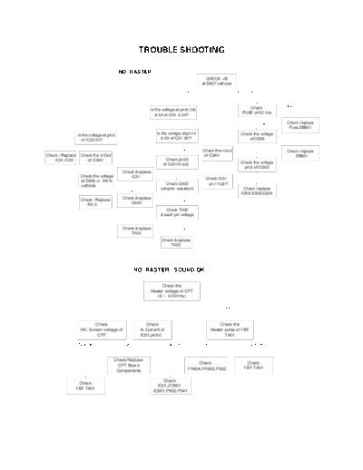
                                                    TROUBLE SHOOTING

                                           NO RASTER
                                                                                           CHECK +B
                                                                                        at D807 cathode
                                                                          Normal                           Abnormal


                                                                                                                 Check           Open
                                                         Is the voltage at pin61,56
                                                                                                              FUSE of AC line
                                                            & 54 of IC01 3.3V?

                                                                          Yes                                          OK        Check /replace
                       No                                                                                                         Fuse,DB801
                  Is the voltage at pin3                      Is the voltage at pin14                        Check the voltage
                     of IC02 5V?                                 & 39 of IC01 8V?                                of C806
                                                                                                  No                                      0V
  Yes
                              No                                           Yes          Check the in/out              254~380V   Check /replace
Check / Replace    Check the In/Out                                                     of IC844                                     DB801
    IC01,IC02         of IC842                                    Check pin33
                                               No                                                            Check the voltage
                                                                 of IC01(H-out)
                              No                                                                  No          pin3 of IC803
                                            Check &replace
                   Check the voltage            IC01                       Yes
                   at D805 or D815                                                        Check IC01
                   cathode                                          Check Q402             pin1 high?
                                               No               collector waveform                            Check /replace
                              No                                                                             IC801,IC803,IC804
                   Check / Replace          Check &replace
                                                                           Yes
                      F812                      Q402
                                                                   Check T402
                                                                & each pin voltage
                                               No
                                            Check &replace                 Yes
                                                T402
                                                                Check &replace
                                                                    T402


                                                 NO RASTER / SOUND OK

                                                              Check the
                                                         Heater voltage of CPT
                                                            (6 ~ 6.5Vrms)

                                                         OK                                        Not OK


                           Check                       Check                                     Check the
                    HV, Screen voltage of           Ik Current of                            Heater pulse of FBT
                            CPT                     IC01,pin50                                      T401

                   Not OK                   OK                      Not OK              OK                         Not OK


                                       Check/Replace
                                                                                     Check                     Check
                                        CPT Board
                                                                                 FR404,FR902,P302             FBT T401
                                        Components

                                                                  Check
                   Check
                                                               IC01,ZD901
                  FBT T401
                                                             IC901,P902,P541
 NO SOUND / PICTURE OK

        MONO


Select correct system
       in menu

            OK
Check the waveform          NO     Check the waveform        NO    Check the waveform
 at pin 44 of IC01                  at pin 35 of IC501              at pin 4 of IC651

            OK                                                                   NO

Check the waveform          NO                                     Check the waveform
                                  Check/Replace Q621
 at pin 1 of IC601                                                  at pin 2,7 of IC651

            OK                                                                   NO

Check the waveform          NO                                     Check the waveform
                                  Check/Replace IC601
 at pin 4 of IC601                                                 at pin28 IC01           NO

            OK
                                                                     OK
 Check the voltage          NO     Check/Replace
                                   FR803,D804                      Check / Replace         Check/Replace
 at pin 5 of IC601                                                                         IC01
                                                                       IC651


      RF STEREO


 Select correct system
        in menu

             OK
 Check the waveform         NO        Check / Replace
  at pin 16 of TU101                      TU101

             OK
 Check the waveform          NO      Check the voltage        NO       Check the voltage
 at pin 24,25 of IC661            at pin 16,33,46 of IC661             at pin1 of IC131
             OK                                                                   NO
 Check the waveform         NO      Check/Replace                         Check/Replace
 at pin 4,12 of IC602               Q671,Q672                             IC131,IC661

             OK

 Check the voltage          NO     Check/Replace
 at pin 6,7 of IC602               Q621,IC603

             OK

  Check the waveform
at pin 1,2,14,15 of IC602

             OK

  Check the voltage         NO      Check/Replace
 at pin 3,13 of IC602               F811,D824
NO PICTURE / NO SONUD
                                                     Is any OSD displayed?

                 No
                                                                 OK
OK     Check IC01 pin50,51,52,53              Check receiving system in MENU
              (IK,R,G,B)                          & excute Auto-program.
                    NO
         Check/ Replace                              Does the Auto-program         OK
              IC01                                     operate properly.

                                                                 NO

                                              Store in manual-program MENU

                Check          NO              Check 5V, 33V & IIC Bus Line
               5V, 33V &                               of TUNER
             IIC Bus Line
                                                                 OK
                                                                                           Go to
                               NO                    Is the CVBS signal OK.
           Check / Replace                                                              NO SOUND /
                                                          ( IC01 pin40 )
           IC01,TUNER                                                                   PICTURE OK
                                                                 OK
           Check        OK         Check IK            NO    Check R,G,B signal
       CVBS singal Line       signal at IC01 pin50          at IC501 pin51,52,53
          & IC01              (similar to CVBS)
                                                                 OK
                                                       Check / Replace
                                                     CPT Board component


          AV STEREO


     Select correct system
            in menu

                 OK
     Check the waveform        NO           Check / Replace
      at pin 44 of IC01                          IC01

                 OK
     Check the waveform        NO          Check the voltage
     at pin 15,18 of IC631                 at pin 6 of IC631

                 OK

     Check the waveform        NO         Check/Replace
     at pin 4,12 of IC602                 IC602

                 OK

     Check the voltage         NO        Check/Replace
     at pin 6,7 of IC602                 Q621,IC603

                 OK

  Check the waveform
at pin 1,2,14,15 of IC602

                 OK

      Check the voltage        NO        Check/Replace
     at pin 3,13 of IC602                F811,D824


◦ Jabse Service Manual Search 2024 ◦ Jabse PravopisonTap.bg ◦ Other service manual resources online : FixyaeServiceinfo