Service Manuals, User Guides, Schematic Diagrams or docs for : LG TV LP-XG1 066ets
<< Back | HomeMost service manuals and schematics are PDF files, so You will need Adobre Acrobat Reader to view : Acrobat Download Some of the files are DjVu format. Readers and resources available here : DjVu Resources
For the compressed files, most common are zip and rar. Please, extract files with Your favorite compression software ( WinZip, WinRAR ... ) before viewing. If a document has multiple parts, You should download all, before extracting.
Good luck. Repair on Your own risk. Make sure You know what You are doing.
Image preview - the first page of the document
>> Download 066ets documenatation <<
Text preview - extract from the document
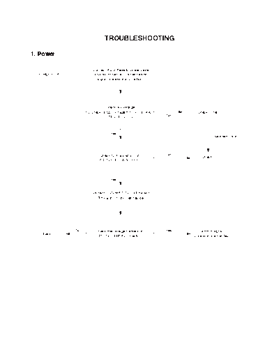
                           TROUBLESHOOTING

1. Power

                    Connect AC voltage to power case
  CHECK. A           and disconnect all connectors of
                      signal processor and ballast.


                           - Check AV voltage.
                  - Check output voltage 6871VPN004A            Check Fuse
                             (250V-380V DC)             No


                              Yes
                                                                        Fuse interruption


                        Check S/W waveform of           No
                                                                   Check B
                        6871VPN007A(100KHz)


                              Yes


                   Connect PON of 6871VPN005A and
                     ST5V with 1K ohm resistance.


             No       Check the voltage marked on       Yes       Short of signal
   Check C
                       6871VPN005A connector                  processor is expected.


                                            - 1 -
CHECK. B

             Symptoms                      Cause / Check                                        Disposal
 A. IC200 is not oscillated.   1. Check the interruption of R200.           1. Replace it.
                               2. Blows up : ---                            2. Check interruption and replace it.
                               3. Rectifier diode failure of the second     3. Check oscillation waveform after replacing IC200
                                  side.                                        and removing D204A and D204B.
                                                                               If oscillation is normal, replace diode.
                               4. Check D201 interruption                   4. Replace D201.

 B. IC200 is oscillated        1. Check short of circuit of the 2nd side.
    intermittently and         2. Check failure of D204C.
    makes noise in trans.

 C. Voltage of the 2nd side    1. IC201 failure.                            1. Replace IC201.
    swings irregularly.


CHECK. C

             Symptoms                      Cause / Check                                        Disposal
 A. 5V is blocked.             1. 5V regulator failure.                     1. Separate D301 and check 5V voltage.
                                                                               Check IC305, 301 and 300.

 B. 12V is blocked.            1. 12V regulator failure.                    1. Check 12V as above.
                                                                               Check IC304.

 C. 15.5V is blocked.          1. Check the collector of Q300 becomes       1. Check and replace D300 or Q300.
                                   0V by R300.
                               2. IC306 failure.                            2. Replace IC306.

 D. Fan 12V is blocked.        1. IC303 failure.                            1. Connect Fon terminal of P102A with
                                                                               ST5V and 1Kohm resistance. Output
                                                                               becomes 0V when pin 4 is low. Check
                                                                               12V after removing resistance and


                                                           - 2 -
2. Digital
2-1. If video signal is not output and screen shows only blue background

  (1) Input H, V sync line is poor ( when displaying no signal )
     --> BA7657 Input tantal capacitor
     --> No M52347 input
  (2) TDA4885 input power is not normal
     --> 12V power input L1206 is in poor connection
     --> No clamp input

2-2. If a color is dark or different with other color signal
  --> Q1130, Q1131, Q1132(KTK211Y )
  --> BA7657 Input tantal capacitor
  --> IC1502, IC1503, IC1504 are not operated.

2-3. When screen is intermittently displayed and signal is not output repeatedly
  --> Operation of Q1388(V-MUTE3) is poor
  --> Operation of IC1505, IC1506, IC1507 is poor

2-4. When a color has problem in some gray on output screen, or has stripes in one color
  --> Connection of IC1042, IC1043, IC1044 is poor

2-5. If set operation is not normal
  --> Input power is not normal and L1002 is poorly connected.
  --> Connection of R1562, R1570, R1572 is poor
  --> Operation of IC11033(KIA7042F) is poor


                                                                   - 3 -
3. LCD Driver
1. Only color stripe is displayed on output screen and image is    5. Output image is reversed horizontally.
   not displayed.
                                                                                                     PC1
                                                                            PC1


                                                                       - Reason : HCK 1/2 pulse of CXD2453Q is changed each other.
   - Reason : H sync of CXA3106Q is not operated.                      - Reason : RGT and XRGT of CXA2111R are changed each
                                                                          other.

2. Only OSD is output on black screen and letters are displayed
   horizontally and vertically in many lines.                      6. Double folded images are displayed by space of 12 pixels.

        PC1          PC1          PC1


              PC1           PC1


   - Reason : Output clock of CXA3106Q is not operated.                - Reason : Adjustment of POS 1/2 of CXA2112R goes wrong.


3. Image is not displayed and only milky screen is output.         7. Vertical bar noise is displayed on the full screen by space of
                                                                      12 pixels.


   - Reason : PCG pulse of CXD2453Q is not output.

                                                                       - Reason : S/H video output of CXA2112 or more output is not
4. Color is not regular and color band is shown on the right end          operated.
   of screen.

                                                                   8. Output image is darker and more faint than normal image.


   - Reason : SID output waveform of CXA2112R is not normal.

                                                                       - Reason : V33 voltage(3.3V) of CXA2111R is not supplied to
                                                                          CXA2112R normally.


                                                               - 4 -
◦ Jabse Service Manual Search 2024 ◦ Jabse Pravopis ◦ onTap.bg ◦ Other service manual resources online : Fixya ◦ eServiceinfo