Service Manuals, User Guides, Schematic Diagrams or docs for : LG TV LT-15A15 ML012ATR
<< Back | HomeMost service manuals and schematics are PDF files, so You will need Adobre Acrobat Reader to view : Acrobat Download Some of the files are DjVu format. Readers and resources available here : DjVu Resources
For the compressed files, most common are zip and rar. Please, extract files with Your favorite compression software ( WinZip, WinRAR ... ) before viewing. If a document has multiple parts, You should download all, before extracting.
Good luck. Repair on Your own risk. Make sure You know what You are doing.
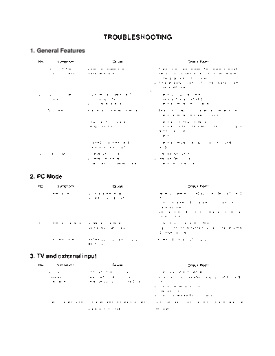
Image preview - the first page of the document

>> Download ML012ATR documenatation <<
Text preview - extract from the document
                                           TROUBLESHOOTING
1. General Features
  No.         Symptom                             Cause                                       Check Point

   1    Soft touch doesn't       Defective speaker wire                 1) Make some space between the speaker wire and
        function properly        and inverter wire                         the Soft touch Board by sticking the speaker wire
                                                                           to the guide hole of the cabinet.
                                                                        2) Arrange working state of A1. correct working state of
                                                                             the Shield case.
   2    Soft touch doesn't       1) Broken components and               1) Check Soft touch with eyes
        function                    soldering of them                      Check and repair soldering
                                 2) P2 connector error                  2) Check and repair the P2 connector
   3    No screen                Input error of inverter connector      1) Bend the pin legs of P1 connector -> recheck them
                                                                        2) Check and repair the IC804,805 SI4925
                                 P502 and Pin 21 connector              1) Check and fix P902 connector
                                 being slipped out                      2) Check and fix the components at P902 LCD module
                                                                           and at main board.
                                                                        3) Check Pin21.
                                 Cracked components and                 1) Check and repair tuner board and main board
                                 soldering at tuner board               2) Solder Q101,102.
   4    Dark screen              1) Defective LCD lamp                  1) Replace the inverter
                                 2) Defective inverter                  2) Replace the LCD lamp
                                 3) Input error of inverter connector   2) Check the connector input.


2. PC Mode
  No.         Symptom                             Cause                                       Check Point

   5    Screen noise             Clock or phase being                   1) Resettig is needed according to the video card of each
                                 not able to be adjusted                   PC
                                                                        2) Horizontal noise : adjust phase until no horizontal
                                                                           noise occurres
                                                                        3) Vertical noise : adjust clock in menu until no vertical
                                                                           noise occurres
   6    Screen position error    Screen position error                  1) Play the Auto Configure in Menu.
                                 horizontally or vertically             2) Adjust horizontal and vertical position until the screen
                                                                           displayes normally
   7    Color beat noise         Soldering D-SUB Jack of JA202          Recheck adn repair JA202,IC202
                                 and IC202.


3. TV and external input
  No.         Symptom                             Cause                                       Check Point
   8    No sound                 Defective Reset IC of IC603            1) Check volume and speaker
        - Speaker                Defective MSP340D of IC601             - Sound comes out only when being inputted into Audio
        - Earphone               Defective B+(8V,5V) of IC604,605.        L/R
                                                                        2) Check after replacing IC603
                                                                        3) Replace IC601
                                                                        4) Check and replace B+ of IC604,605.
   9    Video color beat noise   Earphone shield case being touched     Check the mould of shield and JA203, Replace shield case
                                 Soldering IC301 and IC912              Re-soldering


                                                              - 15 -
◦ Jabse Service Manual Search 2024 ◦ Jabse Pravopis ◦ onTap.bg ◦ Other service manual resources online : Fixya ◦ eServiceinfo