Service Manuals, User Guides, Schematic Diagrams or docs for : LG TV ca14f33 051ATS

<< Back | Home

Most service manuals and schematics are PDF files, so You will need Adobre Acrobat Reader to view : Acrobat Download Some of the files are DjVu format. Readers and resources available here : DjVu Resources
For the compressed files, most common are zip and rar. Please, extract files with Your favorite compression software ( WinZip, WinRAR ... ) before viewing. If a document has multiple parts, You should download all, before extracting.
Good luck. Repair on Your own risk. Make sure You know what You are doing.


Image preview - the first page of the document
051ATS


>> Download 051ATS documenatation <<

Text preview - extract from the document
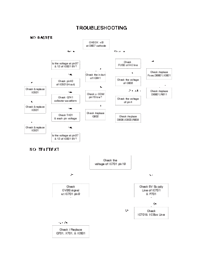
                                      TROUBLESHOOTING
   NO RASTER
                                              CHECK +B
                                           at D807 cathode
                             Normal                            Abnormal


                                                                     Check                 Open
                 Is the voltage at pin37
                                                                  FUSE of AC line
                    & 12 of IC501 8V?
                                                     No
                                                                            OK              Check /replace
                              Yes          Check the in/out                               Fuse,DB801,IC801
                                              of IC841
                     Check pin40                                 Check the voltage
   No                                                                of C806
                    of IC501(H-out)                                                                 0V
                                                     No
Check &replace
                              Yes                                          254~380V        Check /replace
    IC501
                                           Check u-COM                                      DB801,R811
                       Check Q741           pin15 low?
                                                                 Check the voltage
   No              collector waveform                                of pin4
Check &replace                                       No
                              Yes
    IC501
                                           Check /replace
                      Check T401               Q802               Check /replace
                   & each pin voltage
                                                                 D806,IC803,R809
   No
Check &replace                Yes
    IC501
                 Is the voltage at pin37
                    & 12 of IC501 8V?


  NO TELETEXT

                                                        Check the
                                                  voltage of IC701 pin19


                               OK                                                          0V


                             Check                                                   Check 5V Supply
                         CVBS signal                                                  Line of IC701
                         at IC701 pin9                                                   & P701


                                                                                             OK

                                                                       OK             Check
                                                                                 IC701& IICBus Line

                      Not OK

                      Check / Replace
                    Q701, X701, & IC501


                                                    - 1 -
NO RASTER / SOUND OK

                                              Check the
                                         Heater voltage of CPT
                                            (6 - 6.5Vrms)

                                         OK                                        Not OK


              Check                    Check                                     Check the
       HV, Screen voltage of        Ik Current of                            Heater pulse of FBT
               CPT                  IC501, pin18                                    T701

      Not OK                   OK                   Not OK              OK                         Not OK


                       Check/Replace                                   Check
                                                                                                Check
                        CPT Board                                   FR704, FR901
                                                                                               FBT T701
                        Components                                  P302, & P902


                                               Check
      Check
                                            IC501, ZD904
     FBT T701
                                            P501, & P902


NO SOUND / PICTURE OK

                                           Select correct
                                          system in MENU


                                        Check the waveform
                                         of Q651 collector

                                                                             Check / replace
                                                                                 Q651
           Check the voltage            Check the waveform
            of IC101(logic)               of pin3 of IC202


            Check / replace
              Q653,654                   Check demodulated
                                           signal of pin15


                                         Check demodulated
                                     of input pin of IC601 or 602


                                           Check the Vcc
                                           of IC601/602


                                               - 2 -
NO PICTURE / NO SONUD
                                              Is any OSD displayed?

                  No
                                                          Yes
   OK   Check IC01 pin30,31,32            Check receiving system in MENU
               (R,G,B)                        & excute Auto-program.
                    Not OK
         Check IC01 pin9,10                   Does the Auto-program        Yes
          (V-Sync, H-Sync)                      operate properly.
         Check IC01 pin36,37
            (XLC, EXLC)                                   Not OK
               & IC01
                                          Store in manual-program MENU

                Check            Not OK    Check 5V, 33V & IIC Bus Line
               5V, 33V &                           of TUNER
             IIC Bus Line
                                                          OK
                                                                                    Go to
                                 Not OK       Is the CVBS signal OK.
           Check / Replace                                                       NO SOUND /
                                                   ( IC501 pin6 )
           TUNER, IC501                                                          PICTURE OK
                                                          OK
               Check             Not OK
                                                Check R,G,B signal
           CVBS singal Line                    at IC501 pin19,20,21
              & IC501
                                                          OK
                                                Check / Replace
                                              CPT Board component


                                               - 3 -


◦ Jabse Service Manual Search 2024 ◦ Jabse PravopisonTap.bg ◦ Other service manual resources online : FixyaeServiceinfo