Service Manuals, User Guides, Schematic Diagrams or docs for : LG TV cf-28a50f pc58aai

<< Back | Home

Most service manuals and schematics are PDF files, so You will need Adobre Acrobat Reader to view : Acrobat Download Some of the files are DjVu format. Readers and resources available here : DjVu Resources
For the compressed files, most common are zip and rar. Please, extract files with Your favorite compression software ( WinZip, WinRAR ... ) before viewing. If a document has multiple parts, You should download all, before extracting.
Good luck. Repair on Your own risk. Make sure You know what You are doing.


Image preview - the first page of the document
pc58aai


>> Download pc58aai documenatation <<

Text preview - extract from the document
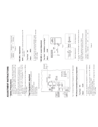
ADJUSTMENT INSTRUCTIONS
* Safety Precautions                                                                                    Frequency       Modulation         Output level
  1. It is safe to adjust after using insulating transformer
                                                                                                         38.9MHz             OFF            10mVp-p
     between the power supply line and chassis input to
     prevent the risk of electric shock and protect the                                                                (Table 1)
     instrument.
  2. Never disconnect leads while the TV receiver is on.
  3. Don't short any portion of circuits while power is on.                                       * SECAM L' Adjustment
  4. The adjustment must be done by the correct
     appliances. But this is changeable in view of                                                  NOTE : This adjustment should be performed after PIF
     productivity.                                                                                         adjustment.
  5. Unless otherwise noted, set the line voltage to 230Vac
       +_10%, 50Hz.
                                                                                                     Test Point : TP1
* Test Equipment required                                                                            Adjust        : VR101
  1.   RF signal generator (with pattern generator)
  2.   DC Power Supply
  3.   Multimeter (volt meter)                                                                      1) Tune the TV set to receive a SECAM-L' signal.
  4.   Oscilloscope                                                                                 2) Adjust VR101 so that the DC voltage may be indicated
  5.   Color analyzer                                                                                 2.6+_0.1Vdc.
                    Main Board(Component side view)

                                                                                                  * SECAM L/L' sound Adjustment

                                                                                     MULTIMETER      Test Point : C638(Refer to the Fig.2)

                                     MAIN BOARD
                                                                                                     Adjust        : VL102
                              TDA9811        VR101
                                                                    L'
                            17            16                       ADJ.
                         TP1
                            23                TP2
            VL102
             4.5M                         9                                                              OSCILLOSCOPE                       IC601
                          TP3     IC101                                                                                                    MSP3410
                    VL101    30                                                                                          C638
                     PIF                  1
                             32
                                                    VR102
                                                                                                                                       55 AM INPUT
 38.9MHz                                                    AGC
 10mVp-p                                                    ADJ.                                                      J116
RF SIGNAL                     5                                                                                                       61
GENERATOR      CERAMIC CAP.        Z102                                                                                            GND
                              4
               10000pF

                                                              (TP point is on the
                          CERAMIC CAP.
                                                              copper side of PCB)
             TUNER        10000pF                                                                                             Fig. 2
                                                              TP1 : pin23 of IC101
                                                              TP2 : pin9 of IC101
             TP5                                              TP3 : pin30 of IC101
 5 0.1Vdc
 DC POWER    J156                                             TP5 : J156
 SUPPLY
            A GC
             TP                                                                                                               Noise
                                                                                                                              Level

Fig. 1 : Connection Diagram of Equipment for PIF Adjustment

                                                                                                       (Before Adjustment)              (After Adjustment)
* PIF (Picture Intermediate Frequency) Adjustment
                                                                                                    1) Connect the Oscilloscope to the Main Board as shown
    Test Point : TP1                                                                                   in Fig. 2.
                                                                                                    2) Set pattern generator as shown Table 2.
    Adjust             : VL101                                                                      3) Adjust VL102 so that the Noise level is minimized.

                                                                                                        System      Signal Pattern Sound signal Carrier signal
  1) Connect the measuring equipment to the Main Board as
     shown in Fig.1.                                                                                   SECAM-L        Color bar             Off           On
  2) Set RF frequency and output level of RF SIGNAL
     GENERATOR as shown Table 1.                                                                                             (Table 2)
  3) Turn on DC power supply.
  4) Adjust VL101 so that the DC voltage may be indicated
       2.6+_0.1Vdc.
 * Vertical/Horizontal/E-W (East-West)                                EW--(Horizontal Width)
                                                                      Adjust to that a digital circle pattern looks like exact circle.
   Adjustment (LINE SVC 1)
                                                                      EP--(East-west Parabola)
    NOTE : These adjustments are already aligned at
                                                                      Adjust so that middle portion of the outermost left and right
           the time of manufacture for optimum
                                                                      vertical line looks like parallel with vertical lines of the CPT.
           performance. Readjustment of them
           should not be necessary unless IC02
                                                                      EC--(East-west Corner)
           (EEPROM) is defective. Because all the
                                                                      Adjust so that the vertical line at every 4 corners of the
           information of these adjustment are
                                                                      screen looks like parallel with the vertical lines of the CPT.
           memorized in that IC.
                                                                      ET--(East-west Trapezium)
   Adjustment Procedures
                                                                      Adjust to make the length of top horizontal line same with it
   1) Tune the TV set to receive a digital circle pattern unless
                                                                      of the bottom horizontal line.
      otherwise noted.
   2) Press OK button on Control Board continuously and OK
      button on remote controller then you can find On
                                                                      * White Balance Adjustment.(LINE SVC 2)
      Screen Display. (Refer to the following Fig.3).
                                                                      NOTE : This adjustment should be performed after screen
   3) Press PR+ or PR- button for desirous function
                                                                             voltage adjustment.
      adjustment.
   4) Press VOL+ or VOL- button for correct picture.
                                                                         1) Tune the TV set to receive an 100% white pattern.
   5) Press OK button to memorize all the adjusted data.
                                                                         2) Press Number 2 button on remote controller in the SVC
   6) After finishing adjustment, press TV/AV button on
                                                                            Mode (press OK button on control board continuously
      remote controller then TV is changed from SVC mode
                                                                            and OK button on remote controller) then you can find
      to normal mode.
                                                                            On Screen Display. (Refer to the following Fig.4).
                                                                         3) Press PSM (RED) button on remote controller. (Standard
          [LINE SVC1]                         1                             picture)
                                             CH5                         4) Press PR+ or PR- button for desirous function
          VL        43    EW      37
                                                                            adjustment.
          VA        21    EP      39                                     5) Adjust VOL+ or VOL- button for GG31.
          SC        35    EC      29                                     6) Adjust VOL+ or VOL-button in each status of "RG--"/"BG--"
          VS        35    ET      20                                        for X=288+_8, Y=295+_8 with color analyzer (color
          HS        31    50HZ*                                             temperature 9000oK).


                                                                               [LINE SVC2]                    1
                                                                                                             CH5
       *: This is only displayed according to
           receiving system.                                                   RG31
                                                                               GG31
           PAL/SECAM System          : 50Hz
        [ NTSC System                : 60Hz
                                                                               BG23
                                                                               DY12*

                        Fig. 3
                                                                                               Fig. 4
VL--(Vertical Linearity)
                                                                            * : Never change this data, this is an important
Adjust so that the boundary line between upper and lower
                                                                                reference data for TV.
half is in accord with geometric horizontal center of the CPT.
                                                                            Ref) PAL I/I': DY15

VA--(Vertical Amplitude)
                                                                         NOTE : If press Number 3 button on the remote controller
Adjust so that the circle of a digital circle pattern may be
                                                                                in the SVC mode then you can find On Screen
located within the effective screen of the CPT.
                                                                                Display. (Refer to the following Fig.5).

SC--(Vertical "S" correction)
Adjust so that all distance between each horizontal lines are                   [LINE SVC3]                    1
to be the same.                                                                                               CH5

                                                                                FP           30
VS--(Vertical Shift)                                                            NP           110
Adjust so that the horizontal center line of a digital circle                   SP           23
pattern is in accord with geometric horizontal center of the                    SV           75
CPT.
                                                                                               Fig. 5
HS--(Horizontal Shift)
Adjust so that the vertical center line of a digital circle pattern          * Never change these data, these are important
is in accord with geometric vertical center of the CPT                         reference data for TV
* RF AGC (Automatic Gain Control) Adjustment                        * Focus Adjustment
                                                                       NOTE: This adjustment should be performed after
   Test Point : TP5 (J156) or Observing Display
                                                                             warming up for 10 minutes.
   Adjust        : VR102
                                                                            Test Point : Observing Display

  The RF AGC control (VR102) was aligned at the time of                     Adjust     : Focus control of FBT
  manufacture for optimum performance over a wide range
  conditions. Readjustment of VR102 should not be
  necessary unless unusual local conditions exist, such as ;           1) Tune the TV set to receive an inactive channel station.
                                                                       2) Adjust the Focus control of FBT for best overall focus.
  1) Channel interference in a CATV system.
  2) Picture bending and/or color beats, which are unusually
     due to excessive RF signal input when the receiver is
     too close to a transmitting tower or when the receiver
     is connected to an antenna distribution system where
     the RF signal has been amplified. In this case, the input
     signal should be attenuated (with pad or filter) to a
     satisfactory level.
  3) Picture noise caused by "broadcast noise" or weak
     signal.
     If the broadcast is "clean" and the RF signal is at least
     1mV (60dBu), the picture will be noise free in any area.

  Adjusting the VR102(RF AGC) control to one end of
  rotation will usually cause a relatively poor signal to noise
  ratio;
  Adjusting to the other end of rotation will usually cause a
  degradation of over load capabilities resulting in color
  beats or adjacent channel interference. For best results,
  adjust the VR102 control while performing on all over local
  channels, or the voltage at J156 will be 6.4


◦ Jabse Service Manual Search 2024 ◦ Jabse PravopisonTap.bg ◦ Other service manual resources online : FixyaeServiceinfo