Service Manuals, User Guides, Schematic Diagrams or docs for : LG TV cf-20e60 M64AAI

<< Back | Home

Most service manuals and schematics are PDF files, so You will need Adobre Acrobat Reader to view : Acrobat Download Some of the files are DjVu format. Readers and resources available here : DjVu Resources
For the compressed files, most common are zip and rar. Please, extract files with Your favorite compression software ( WinZip, WinRAR ... ) before viewing. If a document has multiple parts, You should download all, before extracting.
Good luck. Repair on Your own risk. Make sure You know what You are doing.


Image preview - the first page of the document
M64AAI


>> Download M64AAI documenatation <<

Text preview - extract from the document
                                                          ADJUSTMENT INSTRUCTIONS

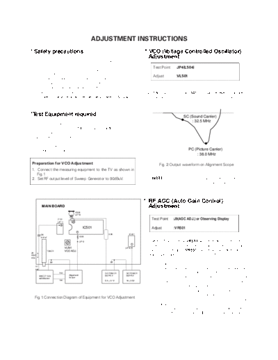
* Safety precautions                                                                       * VCO (Voltage Controlled Oscillator)
                                                                                               Adjustment
   1. It is safe to adjust after using insulating transformer
      between the power supply line and chassis input to                                          Test Point     :
                                                                                                                 JP4(L504)
      prevent the risk of electric shock and protect the
      instrument.                                                                                 Adjust         :
                                                                                                                 VL501
   2. Never disconnect leads while the TV receiver is on.
   3. Don't short any portion of circuits while power is on.
   4. The adjustment must be done by the correct appliances.                                   1) Turn on DC power supplies.
      But this is changeable in view of productivity.                                          2) Adjust VCO ADJ. coil(L501) so that the level of Picture
   5. Unless otherwise noted, set the line voltage to 220Vac+_                                    Carrier (PC) may be at the lowest position as shown Fig.
      20%, 50/60Hz.                                                                               2.


*Test Equipment required                                                                                             SC (Sound Carrier)
                                                                                                                         : 32.5 MHz
   1.     Swee p Generator
   2.     Marker Generator(38.0MHz: Picture/32.5MHz: Sound)
   3.     Alignmen t Scope(5121A)
   4.     Patter n Generator(PAL/SECAM)
   5.     DC Power Supply
   6.     Color analyzer
   7.     Multimeter(Volt meter)                                                                                         PC (Picture Carrier)
                                                                                                                             : 38.0 MHz

Preparation for VCO Adjustment                                                                        Fig. 2: Output waveform on Alignment Scope
1. Connect the measuring equipment to the TV as shown in
   Fig. 1
2. Set RF output level of Sweep Generator to 90dBuV.                                             NOTE:     When performing this adjustment, if there are 2
                                                                                                           adjusted point in VL501, select the lower core
                                                                                                           position.


                                                                                           * RF AGC (Auto Gain Control)
           MAIN BOARD                                                                          Adjustment
                                            C533
                                            (JP 3)

                        Z101                                                                     Test Point    :J9(AGC ADJ.) or Observing Display
                        (JP 1)         48

                           5
                                                     IC501                                       Adjust        :VR501
                                             7
          CK                                                    3.3K         IC401
          0.01uF                                 L504

                                                 (JP 4)                                        The RF AGC control VR501 was aligned at the time of
                                                                                   1
                                 VL501
                                                                                               manufacture for optimum performance over a wide range
                                                                          (JP 6)
                TUNER            VCO ADJ.                                                      conditions. Readjust VR501 should not be necessary
J9
AGC                                                                                            unless unusual local conditions exist, such as;
ADJ.


                                                                                                 1) Channel interference in a CATV system
   RF
   out                                                                                           2) Picture bending and/or color beats, which are unusually
                         Hor                                 DC POWER     DC POWER                  due to excessive RF signal input when the reciever is
         SWEEP S.G                  Alignment                SUPPLY       SUPPLY
         with Marker                Scope                                                           too close to a transmitting tower or when the receiver
                         Ver                                 5.0 + 0.1V   16 + 0.5V
                                                                                                    is connected to an antenna distribution system where
                                                                                                    the RF signal has been amplified.
                                                                                                    In this case, the input signal should be attenuated(with
                                                                                                    pad or filter) to a satisfactory level.
   Fig. 1: Connection Diagram of Equipment for VCO Adjustment
                                                                                                 3) Picture noise caused by "broadcast noise" or weak
                                                                                                    signal.
                                                                                                    If the broadcast is "clean" and the RF signal is at least
                                                                                                    1mV (60dBu), the picture will be noise free in any area.


                                                                                       - 1 -
    Adjusting the VR501(RF AGC) control to one end of               * Scr een & White Balance
    rotation will usually cause a relatively poor signal to noise
    ratio;
                                                                       (color temperature) Adjustment
    Adjusting to the other end of rotation will usually cause a
                                                                       NOTE: 1. This adjustment should be performed after
    degradation of over load capabilities resulting on color
                                                                                warming up for 20 minutes.
    beats or adjacent channel interference.
                                                                             2. The color bias controls (VR901, VR902, VR903)
    For the best results, adjust VR501 contol while
                                                                                affect the low light (dark) area of the picture
    performing on all other local channels, or Refer to the
                                                                                while the color drive controls (VR904, VR905)
    following Table 1.
                                                                                affect the high light (white) areas.

   Tuner P/N        Maker     Adjustment Voltage     REMARK             1) Set all the controls (VR901-VR905) on CPT Board to
 113-118C/D/F     LG-ALPS 5.7+_0.1Vdc              RF 60+_1dBuV            geometric center position.
                                                                        2) Set the standard mode (contrast : 80, bright : 60, color : 50).
 113-238H         LG-ALPS 6.0+_0.1Vdc              RF 60+_1dBuV
                                                                        3) Set the AV mode, adjust and set the screen volume of
 6700VMV001A SANYO            4.9+_0.1Vdc          RF 60+_1dBuV            FBT at just cut-off position(No AV input signal).
                                                                        4) Set the TV mode, tune the TV set to receive white
                          
                                                                           pattern.
                                                                        5) By using color analyzer (white balance checker), adjust
                                                                           X position equals to 281+_8 and Y position equals to 288
* Vertical Height, Center Adjustment                                       +_8, it means that color temperature is 10,000+_800 at
                                                                           low light (4.5ftL) and high light (over 45ftL).
    Test Poin t : Observing display

    Adjust        : VR30 (Vertical Height)
                        1
                    VR302 (Vertical Center)


    1) Tune the TV set to receive a digital test pattern.
    2) Set standard picture mode(contrast: 80, bright :60,
       color: 50).
    3) Adjust the Vertical height control (VR301) so that the
       circle of a digital test pattern may be located within
       the effective screen of the CPT.
    4) Adjust the Vertical center control (VR302) for
       obtaining geometric center of valuable display
       vertically.


* Focus A djustment
  NOTE: This adjustment should be performed after
        warming up for 10 minutes.


    Test Poin t : Observing display

    Adjust        : Focus control of FBT


    1) Tune the TV set to receive a digital test pattern.
    2) Adjust the Focus control for the best overall focus.


* Horizontal Center Adjustment
    Test Poin t : Observing display

    Adjust       : VR502


    1) Tune the TV set to receive a PAL digital pattern.
    2) Adjust the Horizontal center control(VR502) for
       obtaining geometric center of valubale display
       horizontally.


                                                               - 2 -
                             PURITY & CONVERGENCE ADJUSTMENT

Caution:
Convergence and Purity have been factory aligned. Do not            5. Reconnect the internal degaussing coil.
attempt to tamper with these alignments.
However, the effects of adjacent receiver components, or            6. Position the beam bender locking rings at the 9 o'clock
replacement of picture tube or deflection yoke may require the         position and the other three pairs of tabs (2,4 and 6 pole
need to readjust purity any convergence.                               magnets) at the 12 o'clock position.


                                 DEFLECTION YOKE                                        6-POLE
                                            PURITY &CONVERGENCE                          6-POLE
                                                                                        MAGNETS
                                                                                         MAGNES              PURITY MAGNET(2-POLE)
                                            MAGNET ASSEMBLY


                                                        6-POLE

                                      ,,,,
                                      ,,,, ,
                                     ,,,, ,
                                     ,,,, ,        ,
                                                ,,,,
                                                 ,,,,
                                               ,,,,                       4-POLE
                                                             X-AXIS YOKE MAGNET
                                          ,
                                      ,,,, ,   ,,,,
                                      ,,,, ,    ,, ,
                                               ,, ,,
                                     ,,,, ,    ,, ,,
                                     ,,,, ,      ,
                                                ,,,,
                                      ,, ,                   POSITIONING
                                                             (L/R PURITY)
 RUBBER
 WEDGES                                         PURITY MAGNET
                                               4-POLE
                                      GLASS CLOTH TAPE                             CONVERGENCE MAGNET ASSEMBLY
                                                                                     CONVERGENCE MAGNET ASSEMBLY


* Purity Adjustment

This procedure DOES NOT apply to bonded yoke and picture            7. Perform the following steps, in the order given, to prepare the
tube assemblies.                                                       receiver for the purity adjustment procedure.
The instrument should be at room temperature (60 degrees F or
above) for six (6) hours and be operating at low beam current          a. Face the receiver in the "magnetic north" direction.
(dark background) for approximately 20 to 30 minutes before
performing purity adjustments.                                         b. Externally degauss the receiver screen with the television
                                                                          power turned off.
CAUTION: Do not remove any trim magnets that may be
attached to the bell of the picture tube.                              c. Turn the television on for approximately 10 seconds to
                                                                          perform internal degaussing and then turn the TV off.
1. Remove the AC power and disconnect the internal
   degaussing coil.                                                    d. Unplug the internal degaussing coil. This allows the
                                                                          thermistor to cool down while you are performing the purity
2. Remove the yoke from the neck of the picture tube.                     adjustment. DO NOT MOVE THE RECEIVER FROM ITS
                                                                          "MAGNETIC NORTH" POSITION.
3. If the yoke has the tape version beam bender, remove it and
   replace it with a adjustable type beam bender (follow the           e. Turn the receiver on and obtain a red raster by increasing
   instructions provided with the new beam bender)                        the red bias control (CW) and decreasing the bias controls
                                                                          for the remaining two colors (CCW).
4. Replace the yoke on the picture tube neck, temporarily
   remove the three (3) rubber wedges from the bell of the             f. Attach two round magnets on the picture tube screen at 3
   picture tube and then slide the yoke completely forward.               o'clock and 9 o'clock positions, approximately one (1) inch
                                                                          from the edge of the mask (use double-sided tape).


3-2
               1.ADJUST YOKE Z-AXIS FIRST                                                 2 .ADJUST BEAM BENDER 2 POLE
               TO GET EQUAL BLUE                                                          MAGNET TO GET FOUR EQUAL
               COLOR CIRCLES                                                              COLOR CIRCLES


                          MAGNETS


                             RED                                                                         RED

8. Referring to above, perform the following two steps:                 6. Reconnect the internal degaussing coil and apply AC power.
   a. Adjust the yoke Z-axis to obtain equal blue circles.
   b. Adjust the appropriate beam bender tabs to obtain correct         7. Turn the receiver on for 10 seconds to perform internal
      purity (four equal circles).                                         degaussing and then turn the receiver off again.

9. After correct purity is set, tighten the yoke clamp screw and        8. Unplug the internal degaussing-coil.
   remove the two screen magnets.
                                                                        9. Turn on the receiver, connect a signal generator to the VHF
10. Remove the AC power and rotate the receiver 180 degrees                antenna terminal and apply a crosshatch signal.
    (facing "magnetic south").
                                                                        Caution: During the convergence adjustment procedure, be
11. Reconnect the internal degaussing coil.                                      very careful not to disturb the purity adjustment tabs
                                                                                 are accidentally move, purity should be confirmed
12. Turn the receiver on for 10 seconds (make sure the receiver                  before proceeding with the convergence adjustments.
    came on) to perform internal degaussing, and then turn the
    receiver off.                                                          Note: Make sure the focus is set correctly on this instrument
                                                                           before proceeding with the following adjustment.
13. Unplug the internal degaussing coil.
                                                                        10. Converge the red and blue vertical lines to the green vertical
14. Turn on the receiver and check the purity by holding one (1)            line at the center of the screen by performing the following
    round magnet at the 3 o'clock and a second round magnet at              steps (below TABLE).
    9 o'clock position. If purity is not satisfactory, repeat steps 8       a. Carefully rotate both tabs of the 4-pole ring magnet
    through 14.                                                                 simultaneously in opposite directions from the 12 o'clock
                                                                                position to converge the red and blue vertical lines.
15. Turn off the receiver and reconnect the internal degaussing             b. Carefully rotate both tabs of the 6-pole ring magnet
    coil.                                                                       simultaneously in opposite directions form the 12 o'clock
                                                                                position to converge the red and blue (now purple)
                                                                                vertical lines with the green vertical line.
* Convergence Adjustment
                                                                        11. Converge the red and blue horizontal with the green line at
Caution: This procedure DOES NOT apply to bonded yoke and                   the center of the screen by performing the following steps.
         picture tube assemblies.                                           (below TABLE)
         Do not use screen magnets during this adjustment                   a. Carefully rotate both tabs of the 4-pole ring magnet
         procedure. Use of screen magnets will cause an                         simultaneously in the same direction (keep the spacing
         incorrect display.                                                     between the two tabs the same) to converge the red and
                                                                                blue horizontal lines.
1. Remove AC power and disconnect the internal degaussing                   b. Carefully rotate both tabs of the 6-pole ring magnet
   coil.                                                                        simultaneously in same direction (keep the spacing
                                                                                between the two tabs the same) to converge the red and
2. Apply AC Power and set the brightness to the Picture Reset                   blue (now purple) horizontal lines with the green
   condition. Set the Color control to minimum.                                 horizontal line.
                                                                            c. Secure the tabs previsouly adjusted by locking them in
3. Apply 8V to the pin.                                                         place with the locking tabs on the beam bender.

4. Adjust the Red, Green and Blue Bias controls to get a dim
   white line.

5. Remove the AC power and 8V from the pin.


                                                                                                                                     3-3
                              RING            ROTATION DIRECTION                         MOVEMENT OF RED
                              PAIRS             OF BOTH TABS                              AND BLUE BEAMS


                                                                                            B              B
                                                             OPPOSITE                           OR
                                                                                            R              R
                                4
                              POLE

                                                               SAME                 B      R         OR    B      R


                                                                                           B               B
                                                             OPPOSITE                                OR
                                                                                           R               R
                                6
                              POLE

                                                               SAME                 B      R         OR    B      R


                 UP/DOWN ROCKING OF THE YOKE                                        LEFT/RIGHT ROCKING OF THE YOKE
                  UP/DOWN ROCKING OF THE YOKE
                 CAUSES OPPOSITE ROTATION OF RED                                    CAUSES OPPOSITE SIZE CHANGE YOKE
                                                                                     LEET/RIGHT ROCKING OF THE OF THE
                 AND BLUEOPPOSITE ROTATION OF RED
                 CAUSES RASTERS                                                     RED AND BLUE RASTERS CHANGE OF
                                                                                    CAUSES OPPOSITE SIZE
                 AND BLUE RASTERS                                                    THE RED AND BLUE RASTERS

                                      GREEN


                                                                                                                                    GREEN
                 ADJUSTMENT
                   VIEWING                                                              ADJUSTMENT                      RED
                    AREA         BLUE    RED                                              VIEWING
                                                                                           AREA
                                                                                                                                    RED

    GREEN                RED                      BLUE

                         BLUE                     RED
                                                                     GREEN


                                 RED      BLUE


                                                                                                                                    TV
                                                                                                                                    SCREEN

                                      GREEN

12. While watching the 6 o'clock positions on the screen, rock the             17. Temporarily place a rubber wedge at the 5 o'clock and 7
    front of the yoke in a vertical (up/down) direction to converge                o'clock positions to hold the horizontal position of the yoke.
    the red and blue vertical lines. (Fig upper left)                          18. Check the 3 o'clock and 9 o'clock areas to confirm that the
13. Temporarily place a rubber wedge at the 12 o'clock position                    red and blue vertical lines are converged. If the lines are not
    to hold the vertical position or the yoke.                                     converged, slightly offset the horizontal tilt of the yoke (move
14. Check the 3 o'clock and 9 o'clock areas to confirm that the red                the temporary rubber wedges if necessary) to equally
    and blue horizontal lines are converged.                                       balance the convergence error of the horizontal lines at 6
    If the lines are not converged, slightly offset the vertical tilt of the       o'clock and 12 o'clock and the vertical lines at 3 o'clock and 9
    yoke (move the rubber wedge if necessary) to equally balance the               o'clock.
    convergence error of the horizontal lines at 3 o'clock and 9 o'clock       19. Using a round magnet confirm purity at the center, right and
    and the vertical lines at 6 o'clock and 12 o'clock.                            left sides and corners. See Purity Adjustment Procedure.
15. Place a 1.5 inch piece of glass tape over the rubber foot at               20. Reconfirm convergence and apply a 1.5 inch piece of glass
    the rear of the 12 o'clock wedge.                                              tape over the rubber foot at the rear of the 5 o'clock and the 7
16. While watching the 6 o'clock and 12 o'clock areas of the                       o'clock wedges.
    screen, rock the front of the yoke in the horizontal (left to
    right) motion to converge the red and blue horizontal lines.
    (Fig. upper right)


3-4


◦ Jabse Service Manual Search 2024 ◦ Jabse PravopisonTap.bg ◦ Other service manual resources online : FixyaeServiceinfo