Service Manuals, User Guides, Schematic Diagrams or docs for : LG TV cf-20j3rg-3b-3r 075atro

<< Back | Home

Most service manuals and schematics are PDF files, so You will need Adobre Acrobat Reader to view : Acrobat Download Some of the files are DjVu format. Readers and resources available here : DjVu Resources
For the compressed files, most common are zip and rar. Please, extract files with Your favorite compression software ( WinZip, WinRAR ... ) before viewing. If a document has multiple parts, You should download all, before extracting.
Good luck. Repair on Your own risk. Make sure You know what You are doing.


Image preview - the first page of the document
075atro


>> Download 075atro documenatation <<

Text preview - extract from the document
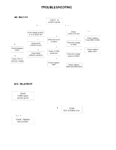
                                        TROUBLESHOOTING


   NO RASTER
                                                CHECK +B
                                             at D807 cathode
                                 Normal                          Abnormal


                                                                       Check              Open
                   Is the voltage at pin37
                                                                    FUSE of AC line
                      & 12 of IC501 8V?
                                                       No
                                                                              OK            Check /replace
                                  Yes        Check the in/out                             Fuse,DB801,IC803
                                                of IC844
                          Check pin40                               Check the voltage
   No                                                                   of C806
                         of IC501(H-out)                                                            0V
                                                       No
Check &replace
                                  Yes                                        254~380V      Check /replace
    IC501
                                             Check u-COM                                    DB801,R811
                            Check Q402        pin28 low?
                                                                    Check the voltage
   No                   collector waveform                           at pin4 of IC804
 Check T401 &                                          No
each pin voltage
                                             Check /replace
                                                 Q807                Check /replace
                                                                   D806,IC804,R809,R810


    NO TELETEXT


            Check
        CVBS signal
        at IC01 pin12


                                                       OK             Check
                                                                IC01 & IICBus Line

     Not OK

      Check / Replace
       Q10 & IC501


                                                    - 16 -
NO SOUND / PICTURE OK

                                       Check the voltage of SMPS
                                          25V at pin9 of IC601

                        Abnormal                                   Normal(20~25V)


            Check/Replace of                                             Check the voltage
             FR803 & D804                                               swing of pin2 of IC501


                                                                         Check demodulated
                                                                        signal of pin15 of IC501


                                                                         Check demodulated
          Check/Replace IC501                                            of input pin of IC601


                                                                            Check/Replace IC01
          Check/Replace IC601


NO RASTER / SOUND OK

                                              Check the
                                         Heater voltage of CPT
                                            (6  6.5Vrms)

                                         OK                                        Not OK


              Check                    Check                                    Check the
       HV, Screen voltage of        Ik Current of                           Heater pulse of FBT
               CPT                  IC501, pin18                                   T701

      Not OK                   OK                   Not OK             OK                         Not OK


                       Check/Replace                                   Check
                                                                                              Check
                        CPT Board                                  FR704, FR901
                                                                                             FBT T701
                        Components                                 P902A & P902B


                                               Check
      Check
                                            IC501, ZD904
     FBT T701
                                           P901A & P901B


                                               - 17 -
NO PICTURE / NO SONUD
                                              Is any OSD displayed?

                  No
                                                          Yes
   OK   Check IC01 pin38,39,40            Check receiving system in MENU
               (R,G,B)                        & excute Auto-program.
                    Not OK
         Check IC01 pin19,20                  Does the Auto-program        Yes
          (V-Sync, H-Sync)                      operate properly.
         Check IC01 pin36,37
            (XLC, EXLC)                                   Not OK
               & IC01
                                          Store in manual-program MENU

                Check            Not OK    Check 5V, 33V & IIC Bus Line
               5V, 33V &                           of TUNER
             IIC Bus Line
                                                          OK
                                                                                    Go to
                                 Not OK       Is the CVBS signal OK.
           Check / Replace                                                       NO SOUND /
                                                   ( IC501 pin6 )
           TUNER, IC501                                                          PICTURE OK
                                                          OK
               Check             Not OK
                                                Check R,G,B signal
           CVBS singal Line                    at IC501 pin19,20,21
              & IC501
                                                          OK
                                                Check / Replace
                                              CPT Board component


                                            - 18 -


◦ Jabse Service Manual Search 2024 ◦ Jabse PravopisonTap.bg ◦ Other service manual resources online : FixyaeServiceinfo