Service Manuals, User Guides, Schematic Diagrams or docs for : LG VCR L224-225-227-228-229-244-247-248-249-295-297-298-299 EC490W_CIRCUIT

<< Back | Home

Most service manuals and schematics are PDF files, so You will need Adobre Acrobat Reader to view : Acrobat Download Some of the files are DjVu format. Readers and resources available here : DjVu Resources
For the compressed files, most common are zip and rar. Please, extract files with Your favorite compression software ( WinZip, WinRAR ... ) before viewing. If a document has multiple parts, You should download all, before extracting.
Good luck. Repair on Your own risk. Make sure You know what You are doing.


Image preview - the first page of the document
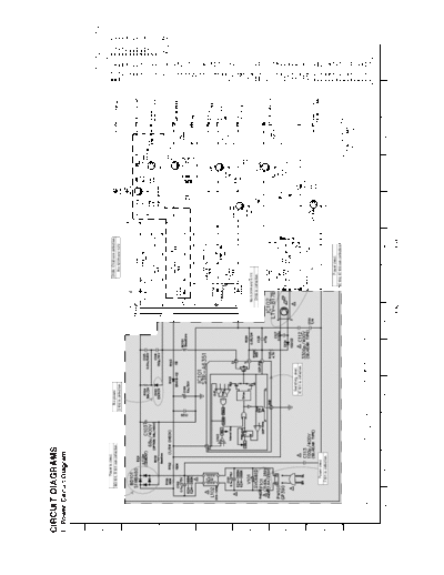
EC490W_CIRCUIT


>> Download EC490W_CIRCUIT documenatation <<

Text preview - extract from the document
CIRCUIT DIAGRAMS
1. Power Circuit Diagram


                               Power is dead.
                                                                                    No power.                                                                                      D109, C120 are defective.
                          BD101, R101 are defective.
                                                                                 D102 is defective.                                                                                   No 12VA and 12V.


                                                                                                                                                                     No 5.3VA and 5.1V.
                                                                                                                                                                     D106 is defective.


                                                                                                Switching dead.
                                                                                               IC101 is defective.


                               Power dead.
                             F101 is defective.

                                                                                                                                                                                     Power dead.
                                                                                                                                                                              IC102, IC103 are defective.


                                                                                                  NOTE :
                                                  NOTE)   Warning                                  1. Shaded( ) parts are critical for safety. Replace only
     NOTES)   Symbol denotes AC ground.           NOTE)   Parts that are shaded are critical          with specified part number.
     NOTES)   Symbol denotes DC chassis ground.   NOTE)   With respect to risk of fire or
                                                  NOTE)   electricial shock.                       2. Voltages are DC-measured with a digital voltmeter
                                                                                                      during TUNER mode.


                                                                                                                                                              3-30                                    3-31
2. Tuner, NICAM, A2 Circuit Diagram


         EE MODE(VIDEO)
         TU MODE (AUDIO)


                                      3-32   3-33
3. A/V Circuit Diagram


                                                          IC301 Pin70 is defective.
                                                        PB COLOR Signal disappear.


                                        D301 or IC301 Pin 80
                                          REC is defective.


                                                                                                          9    3   6
                                                                                            1                                              2   2

                                                                                                                                                          2


                  IC301 Pin 84 is defective.
                   Audio Tracking is failed.

                                                                                                        14 10
                                                                                                                                                              7
                                                                             IC301 Pin 69, 68 are defective.
                                                                               PB and Recording is failed.
                                                                                (IC301 doesn't operate.)


                                                        4


                                                                   5
                                                                                                                                                   8 13
                                                                                                                                 11   12


                                                                                                                                                         X301 is defective.
                                                                                                                                                     PB COLOR Signal disappear.


    Q302, Q303, Q304
    are defective.
    No mono Audio Signal
    in PB MODE.                                                                          FL301, Q301, Q306 are defective.
                                                                                        Normal Audio signal is not recorded.

       PB Y+C                   REC Y+C                     REC AUDIO

       PB Y                     REC Y                       PB AUDIO(MONO)

       PB C                     REC C                          WAVEFORM
       PB SECAM COLOR           REC SECAM COLOR


                                                                                                                               3-34                        3-35
4. System Circuit Diagram


◦ Jabse Service Manual Search 2024 ◦ Jabse PravopisonTap.bg ◦ Other service manual resources online : FixyaeServiceinfo