Service Manuals, User Guides, Schematic Diagrams or docs for : LeCroy LECROY 9400A Operating
<< Back | HomeMost service manuals and schematics are PDF files, so You will need Adobre Acrobat Reader to view : Acrobat Download Some of the files are DjVu format. Readers and resources available here : DjVu Resources
For the compressed files, most common are zip and rar. Please, extract files with Your favorite compression software ( WinZip, WinRAR ... ) before viewing. If a document has multiple parts, You should download all, before extracting.
Good luck. Repair on Your own risk. Make sure You know what You are doing.
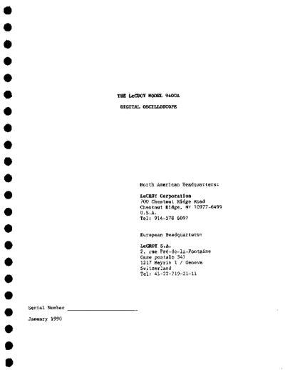
Image preview - the first page of the document

>> Download LECROY 9400A Operating documenatation <<
Text preview - extract from the document
THE LeCROY MODEL 9400A
DIGITAL OSCILLOSCOPE
North American Headquarters:
LeCROY Corporation
700 Chestnut Ridge Road
Chestnut Ridge, NY 10977-6499
U.S.A.
Tel: 914-578 6097
European Headquarters:
LeCROY S.A.
2, rue Pr~-de-la-Fontaine
Case postale 341
1217 Meyrin 1 / Geneva
Switzerland
Tel: 41-22-719-21-11
Serial Number
January 1990
TABLE OF CONTENTS
Section Page Number
I. GENERAL INFORMATION
Technical Data Sheet
1.1 Warranty I-I
1.2 Assistance and Maintenance Agreements i-I
1.3 Documentation Discrepancies 1-2
1.4 Service Procedure 1-2
1.5 Return Procedure 1-2
1.6 Initial Inspection 1-3
2. PRODUCTDESCRIPTION
2.1 Introduction 2-1
2.2 9400A Architecture 2-1
2.3 ADCs and Memories 2-2
2.4 Trigger 2-3
2.5 Automatic Calibration 2-3
2.6 Display 2-3
2.7 Manual and Programmed Control 2-3
3. INSTALLATION
3.1 Safety Information 3-1
3.2 Operating Voltage 3-1
3.3 Switching on the 9400A 3-2
4. DISPLAY LAYOUT
4.1 Menu Field 4-1
4.2 Time and Frequency Field 4-2
4.3 Trigger Delay Field 4-2
4.4 Abridged Front Panel Status Field 4-2
4.5 Displayed Trace Field 4-2
4.6 Message Field 4-3
5. MANUAL OPERATION
5.1 Front-panel Controls 5-1
5.1.1 Vertical 5-1
5.1.2 Time Base 5-4
5.1.3 Trigger 5-6
5.1.4 Displaying Traces 5-12
5.1.5 Display Control 5-12
5.1.6 Screen Adjustments 5-1
5.1.7 Cursors 5-15
ii
5.2 Menu Controls 5-18
5.2.1 Store Menu 5-18
5.2.2 Panel Status Menu 5-20
5.2.3 Memory Status 5-22
5.2.4 Storage and Recall of Front Panel Setups 5-24
5.2.5 Special Modes 5-25
5.2.5.1 Auto-store Mode 5-25
5.2.5.2 Common Expand Mode 5-26
5.2.6 RS-232-C Setup 5-26
5.2.7 Plotter Setup 5-28
6. REAR PANEL CONTROLSAND CONNECTORS
6.1 Fuse Protection 6-1
6.2 Accessory Power Connectors 6-1
6.3 Battery Pack 6-1
6.4 GPIB and RS-232-C Port Selection 6-1
6.5 Plotter Connector 6-2
7. REMOTEOPERATIONS
7.1 Programmed Control 7-1
7.2 RS-232-C Ports 7-1
7.3 GPIB Port (Option OP02 only) 7-2
7.4 C~IB and RS-232-C Command Format 7-3
7.4.1 Introduction 7-3
7.4.2 Compound Commands 7-4
7.4.3 Command Format 7-4
7.4.4 Answers from the 9400A 7-5
7.4.5 Flushing of 9400A Output Buffer 7-6
7.4.6 Command Synchronization with Data Acquisition 7-6
7.4.7 Character Strings 7-7
7.4.8 Prompt 7-7
7.4.9 Errors and Adapted Values 7-8
7.5 Data Block Transfers 7-8
7.6 Commands 7-11
7.6.1 Notation 7-11
7.6.2 Acquisition Parameter Commands 7-12
7.6.3 Display Commands 7-15
7.6.4 Plotter Commands 7-20
7.6.5 Transfer Commands 7-22
7.6.6 Other Remote Commands 7-30
7.6.7 Communication Format Command 7-31
7.6.8 Status Byte and Mask Register Commands 7-34
7.6.9 GPIB Interface Message Interpretation 7-38
7.6.10 RS-232-C Only Commands 7-39
iii
7.7 Binary Format of Waveform Descriptors 7-43
7.8 Format of Trigger Time(s) 7-47
7.9 Data Addressing Conventions 7-48
7.10 Interpretation of Waveform Data Values 7-50
7.10.1 Waveform Data in 8-bit Format 7-50
7.10.2 Waveform Data in 16-bit Format 7-52
7.11 Use of the Service Request (SRQ) Interrupts 7-52
7.11.1 Service Request in GPIB 7-52
7.11.2 Service Request in RS-232-C 7-55
8. BASIC 9400A WAVEFORM MEASUREMENTS AND OPERATING PROCEDURES
8.1 Repetitive Signal Acquisition 8-1
8.2 Single Shot Acquisition 8-3
8.3 Trace Expansion - Expand A/B 8-5
8.4 Sequential Recording of Single Events in
Segmented Memory 8-6
8.5 Slow Signal Recording 8-8
8.6 Window Triggering 8-9
8.7 Storing and Recalling Front Panel Setups 8-9
8.8 Signal Storage in Memories C, D 8-10
8.9 Redefinition Function - Expand Memories C, D 8-11
8.10 Auto-Store in Memory C, D 8-12
8.11 Common Expand Mode 8-13
8.12 Remote Control Via RS-232-C Port 8-14
8.13 Remote Control Via GPIB (Option OP02 Only) 8-18
8.14 Making a Plot when the Computer, the 9400A,
and the Plotter are All Connected Together
on a GPIB Bus (Option OP02 Only) 8-19
8.15 Configuring the Parallel Polling (Option 0P02 0nly) 8-20
9. GETTING THE MOST OUT OF YOUR 9400A
9.1 Front Panel Controls 9-1
9.2 Accurate Amplitude Measurements 9-1
9.3 Accurate Time Measurements 9-3
9.4 Auto-calibration 9-4
I0. WPOI WAVEFORM PROCESSING OPTION
I0.i Processing Capabilities I0-i
10.2 Setting up a Waveform Processing Function 10-2
Manually
10.2.1 Summed Average 10-3
10.2.2 Continuous Average 10-4
10.2.3 Extrema 10-5
10.2.4 Arithmetic 10-6
10.2.5 Functions 10-6
10.2.6 Smoothing 10-6
iv
10.3 Remote Control of Waveform Processing Functions 10-8
10.4 Additional Values in the Descriptors of
Processed Waveforms 10-13
10.5 Vertical Scaling Units 10-15
10.6 Index of Topics 10-17
11. Fast Fourier Waveform Processing Option
(WP02, V 2.06FT)
ii.i Processing Capabilities II-I
11.2 Modification to WP01 Functions 11-3
11.3 FFT Processing Examples 11-4
11.4 Remote Control of FFT Processing 11-7
11.4.1 Remote Commands 11-7
11.4.2 Additional Values in the Descriptors of
FFT Processed Waveforms 11-9
11.5 FFT Application Hints ii-ii
11.5.1 Some practical suggestions II-ii
11.5.2 Relationships of 9400A FFT output waveforms to
the FFT computation steps 11-12
11.5.3 Computation Speed of FFT 11-15
11.6 FFT 9400A Glossary 11-16
11.7 Errors and Warnings 11-21
11.8 Table of Nyquist Frequencies 11-22
11.9 References 11-29
ii. I0 Index of Topics 11-30
Appendix
44 43 42 ~ 40 39
100Ms/s
LeCroy
9400A DUAL 175MHz OSCILLOSCOPE
sG,/s SELECT VERT GAIN PosmoN REFERENCE DIFFERENCE
...~+
◦ Jabse Service Manual Search 2024 ◦ Jabse Pravopis ◦ onTap.bg ◦ Other service manual resources online : Fixya ◦ eServiceinfo