Service Manuals, User Guides, Schematic Diagrams or docs for : PENTAX P30 pentax_p3_p30
<< Back | HomeMost service manuals and schematics are PDF files, so You will need Adobre Acrobat Reader to view : Acrobat Download Some of the files are DjVu format. Readers and resources available here : DjVu Resources
For the compressed files, most common are zip and rar. Please, extract files with Your favorite compression software ( WinZip, WinRAR ... ) before viewing. If a document has multiple parts, You should download all, before extracting.
Good luck. Repair on Your own risk. Make sure You know what You are doing.
Image preview - the first page of the document

>> Download pentax_p3_p30 documenatation <<
Text preview - extract from the document
Similar models: P5 (mechanically the
same). Super Program and A3000
(electronically similar)
Product #: P30 (domestic version) --
                                              PENTAX P3, P30
25300; P3 (American version) --
25301
Batteries: 2ea S76 (negative ground)
                                                                   APERTURE-
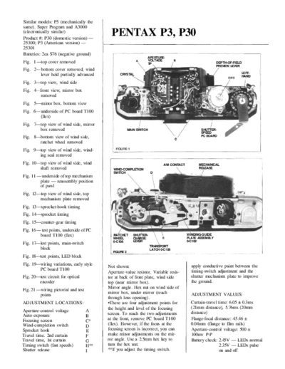
Fig. I --top cover removed                                   A     VOLTAGE            B
                                                                   TP                                        DEPTH-OF-FIELD
                                                                                                             PREVIEW LEVER
Fig. 2    bottom cover removed, wind
                                                                                                                          LEFT-
          lever held partially advanced           CRYSTAL
                                                                                                                          HAND
                                                                                                                   sws
Fig. 3--top view, wind side
Fig. 4 -front view, mirror box
         removed
Fig. 5---mirror box. bottom view
Fig. 6    underside of PC board T100
          (Ilex)
Fig. 7--top view of wind side, mirror
        box removed                                      MAIN SWITCH                               SHUTTER-
                                                                                                   SPEED
Fig. 8--bottom view of wind side,                                                                  PC BOARD
                                                                                      c
        ratchet wheel removed
Fig. 9--top view of wind side, wind-            FIGURE 1

        ing seal removed
Fig. 10 top view of wind side, wind                                           A/M CONTACT         MECHANICAL
        shaft removed                          WIND-COMPLETION                                    RELEASE
                                               SWITCH                  D
Fig. 11 -- underside of top mechanism
          plate -- reassembly position
          of pawl
Fig. 12--top view of wind side, top
         mechanism plate removed
Fig. 13--sprocket-hook timing
Fig. 14--sprocket timing
Fig. 15--counter-gear timing
Fig. 16 -- test points, underside of PC
          board T100 (flex)                    RATCHET      SHUTTER-                        WINDING-GUIDE
                                               WHEEL        CHARGE            E             PLATE ASSEMBLY
                                               0-C106       LEVER                           0-C102
Fig. 17--lest points, main-switch
                                                                       TRANSPORT
         block                                                         LATCH 0-C108
                                              FIGURE 2
Fig. 18--test points, LED block
Fig. 19--wiring variations, early style                                                       apply conductive paint between the
                                            Not shown:
         PC board T100                                                                        timing-switch adjustment and the
                                            Aperture-value resistor. Variable resis-
Fig. 20--test circuit for optical           tor at back of front plate, wind side             shutter mechanism plate to improve
         encoder                            top (near mirror box).                            the ground.
Fig. 21 --wiring pictorial and test         Mirror angle. Hex nut on wind side of
          points                            mirror box, under mirror (reach                   ADJUSTMENT VALUES:
                                            through lens opening).
ADJUSTMENT LOCATIONS:
◦ Jabse Service Manual Search 2025 ◦ Jabse Pravopis ◦ onTap.bg ◦ Other service manual resources online : Fixya ◦ eServiceinfo