Service Manuals, User Guides, Schematic Diagrams or docs for : PHILCO TV PF2118 Philco+PF2118+-+chasis+LA7A
<< Back | HomeMost service manuals and schematics are PDF files, so You will need Adobre Acrobat Reader to view : Acrobat Download Some of the files are DjVu format. Readers and resources available here : DjVu Resources
For the compressed files, most common are zip and rar. Please, extract files with Your favorite compression software ( WinZip, WinRAR ... ) before viewing. If a document has multiple parts, You should download all, before extracting.
Good luck. Repair on Your own risk. Make sure You know what You are doing.
Image preview - the first page of the document
>> Download Philco+PF2118+-+chasis+LA7A documenatation <<
Text preview - extract from the document
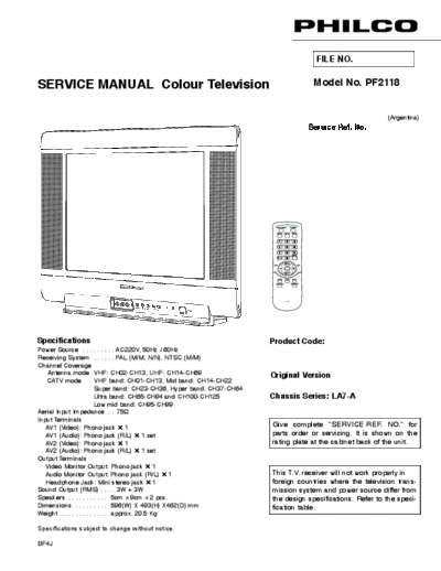
FILE NO.
SERVICE MANUAL Colour Television Model No. PF2118
(Argentina)
Service Ref. No.
AV2 IN VIDEO L AUDIO R
JXMRR
MENU
CH - VOL + POWER
Specifications Product Code:
Power Source . . . . . . . . . AC220V, 50Hz / 60Hz
Receiving System . . . . . . PAL (M/M, N/N), NTSC (M/M)
Channel Coverage
Antenna mode VHF: CH02-CH13, UHF: CH14-CH69 Original Version
CATV mode VHF band: CH01-CH13, Mid band: CH14-CH22
Super band: CH23-CH36, Hyper band: CH37-CH64
Ultra band: CH65-CH94 and CH100-CH125 Chassis Series: LA7-A
Low mid band: CH95-CH99
Aerial Input Impedance . . 75
Input Terminals
AV1 (Video): Phono jack 1 Give complete "SERVICE REF. NO." for
AV1 (Audio): Phono jack (R/L) 1 set parts order or servicing. It is shown on the
AV2 (Video): Phono jack 1 rating plate at the cabinet back of the unit.
AV2 (Audio): Phono jack (R/L) 1 set
Output Terminals
Video Monitor Output: Phono jack 1
Audio Monitor Output: Phono jack (R/L) 1 This T.V. receiver will not work properly in
Headphone Jack: Mini stereo jack 1 foreign countries where the television trans-
Sound Output (RMS) . . . . 3W + 3W mission system and power source differ from
Speakers . . . . . . . . . . . 5cm x 9cm x 2 pcs. the design specifications. Refer to the speci-
Dimensions . . . . . . . . . 596(W) X 493(H) X462(D) mm fication table.
Weight . . . . . . . . . . . . . approx. 20.5 Kg
Specifications subject to change without notice.
BF4J
Contents
Safety Notice . . . . . . . . . . . . . . . . . . . . . . . . . . . . . . . . . . . . . . . . . . . . . . . . . . . . . . . . . . . . . . . . . . . . . . . . . . . 2
Chassis Block Diagram . . . . . . . . . . . . . . . . . . . . . . . . . . . . . . . . . . . . . . . . . . . . . . . . . . . . . . . . . . . . . . . . . 3-4
IC Block Diagrams . . . . . . . . . . . . . . . . . . . . . . . . . . . . . . . . . . . . . . . . . . . . . . . . . . . . . . . . . . . . . . . . . . . . . 5-8
Service Adjustments. . . . . . . . . . . . . . . . . . . . . . . . . . . . . . . . . . . . . . . . . . . . . . . . . . . . . . . . . . . . . . . . . . . 9-17
Purity and Convergence Adjustment . . . . . . . . . . . . . . . . . . . . . . . . . . . . . . . . . . . . . . . . . . . . . . . . . . . . . . . 18
Cabinet Parts List . . . . . . . . . . . . . . . . . . . . . . . . . . . . . . . . . . . . . . . . . . . . . . . . . . . . . . . . . . . . . . . . . . . . . . . 19
Chassis Electrical Parts List. . . . . . . . . . . . . . . . . . . . . . . . . . . . . . . . . . . . . . . . . . . . . . . . . . . . . . . . . . . . 20-26
Safety Notice
SAFETY PRECAUTIONS
1: An isolation transformer should be connected in the 3: When replacing a chassis in the cabinet, always
power line between the receiver and the AC line be certain that all the protective devices are
when a service is performed on the primary of the installed properly, such as, control knobs, adjust-
converter transformer of the set. ment covers or shields, barriers, isolation resistor-
capacitor networks etc.. Before returning any
2: Comply with all caution and safety-related notes television to the customer, the service techni-
provided on the cabinet back, inside the cabinet, on cian must be sure that it is completely safe
the chassis or the picture tube. to operate without danger of electrical shock.
X-RADIATION PRECAUTION
The primary source of X-RADIATION in television receiver is the picture tube. The picture tube is specially con-
structed to limit X-RADIATION emissions. For continued X-RADIATION protection, the replacement tube must
be the same type as the original including suffix letter. Excessive high voltage may produce potentially hazard-
ous X - RADIATION. To avoid such hazards, the high voltage must be maintained within specified limit. Refer
to this service manual, high voltage adjustment for specific high voltage limit. If high voltage exceeds specified
limits, take necessary corrective action. Carefully follow the instructions for + B1 volt power supply adjustment,
and high voltage check to maintain the high voltage within the specified limits.
PRODUCT SAFETY NOTICE
Product safety should be considered when a component replacement is made in any area of a receiver.
Components indicated by mark in the parts list and the schematic diagram designate components in which
safety can be of special significance. It is particularly recommended that only parts designated on the parts list
in this manual be used for component replacement designated by mark . No deviations from resistance
wattage or voltage ratings may be made for replacement items designated by mark .
-2-
AERIAL
CRT DRIVE
HORIZ-DRIVE HORIZ-OUT
Chassis Block Diagrams
MAIN SIGNAL PROCESSING CIRCUIT
(LA76931)
SAW FILTER
FBT IN FBT PULSE
-3-
VIDEO
VERT-OUT
AUDIOPW SPEAK(L)
AV1 / AV2 AUDIO INPUT
AUDIOPW
AUDIO OUTPUT
POWER AUDIO-OUT
SPEAK(R)
Chassis Block Diagrams
IC 601 POWER SUPPLY IC (STRW6753)
FUNCTIONAL BLOCK DIAGRAM
-4-
IC Block Diagrams
IC201 < IF/Video/Chroma/Def./CPU > LA76931
-5-
IC Block Diagrams
IC501 LA78040
T her mal
P r otection
-
A MP
+
P ump
Up
1 2 3 4 5 6 7
OU T P U T S T AG E V cc
V cc
N ON I N V.I N P UT
G ND
Ver.OU T P UT
I N V E R T I N G I N P UT
P U M P U P O UT
S ample application cir cuits
L A 78040B /040/041/045 L A 78040B /040/041/045
IC001 ◦ Jabse Service Manual Search 2026 ◦ Jabse Pravopis ◦ onTap.bg ◦ Other service manual resources online : Fixya ◦ eServiceinfo