Service Manuals, User Guides, Schematic Diagrams or docs for : Philips Audio AZ1510-1515 hfe_philips_az1510_1515_service_en
<< Back | HomeMost service manuals and schematics are PDF files, so You will need Adobre Acrobat Reader to view : Acrobat Download Some of the files are DjVu format. Readers and resources available here : DjVu Resources
For the compressed files, most common are zip and rar. Please, extract files with Your favorite compression software ( WinZip, WinRAR ... ) before viewing. If a document has multiple parts, You should download all, before extracting.
Good luck. Repair on Your own risk. Make sure You know what You are doing.
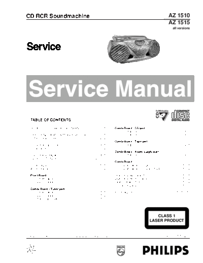
Image preview - the first page of the document

>> Download hfe_philips_az1510_1515_service_en documenatation <<
Text preview - extract from the document
CD RCR Soundmachine                                                                                                                                            AZ 1510
                                                                                                                                                               AZ 1515
                                                                                                                                                                    all versions


    TABLE OF CONTENTS

    Handling Chip Components and Safety ..........................1 - 1                              Combi Board - CD part
                                                                                                        circuit diagram - 1 ...................................................8 - 1
    Technical Specification & Measurement Setup ...............2 - 1                                    circuit diagram - 2 ...................................................8 - 2
    Service Measurement......................................................2 - 2
                                                                                                     Combi Board - Tape part
    Connections and controls ................................................3 - 1                      circuit diagram .........................................................9 - 1
    Service tools ....................................................................3 - 2
                                                                                                     Combi Board - Audio/supply part
    Disassembly Diagram......................................................4 - 1                      circuit diagram .........................................................9 - 2
    CD Service Test program .....................................4 - 2 .. 4 - 3
                                                                                                     Combi Board
    Block Diagram .................................................................5 - 1                layout diagram (copper side).................................10 - 1
    Wiring Diagram ................................................................5 - 2                layout diagram (component side) ..........................10 - 2

    Front Board                                                                                      Exploded view - cabinet.................................................11 - 1
        circuit diagram .........................................................6 - 1               Exploded view - tape deck ............................................11 - 2
        layout diagram.........................................................6 - 2                 Tape deck adjustment ...................................................11 - 2
                                                                                                     Mechanical partslist .......................................................11 - 2
    Combi Board - Tuner part
       circuit diagram .........................................................7 - 1                Electrical partslist ...........................................12 - 1 .. 12 - 10
       layout diagram.........................................................7 - 2
       Tuner adjustment ....................................................7 - 2


                                                                                                                                              CLASS 1
                                                                                                                                           LASER PRODUCT


Published by LX 0304 Service Audio        Printed in The Netherlands       Subject to modification
◦ Jabse Service Manual Search 2024 ◦ Jabse Pravopis ◦ onTap.bg ◦ Other service manual resources online : Fixya ◦ eServiceinfo