Service Manuals, User Guides, Schematic Diagrams or docs for : Philips Audio DCM71312 philips_dcm713_12
<< Back | HomeMost service manuals and schematics are PDF files, so You will need Adobre Acrobat Reader to view : Acrobat Download Some of the files are DjVu format. Readers and resources available here : DjVu Resources
For the compressed files, most common are zip and rar. Please, extract files with Your favorite compression software ( WinZip, WinRAR ... ) before viewing. If a document has multiple parts, You should download all, before extracting.
Good luck. Repair on Your own risk. Make sure You know what You are doing.
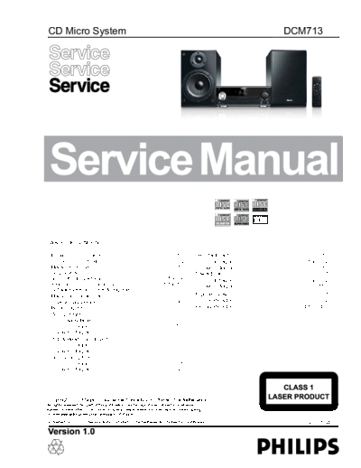
Image preview - the first page of the document

>> Download philips_dcm713_12 documenatation <<
Text preview - extract from the document
CD Micro System                                                                                                                               DCM713


TABLE OF CONTENTS

 Location of PC Boards .................................................... 1-1         Decoder Board .................................................................10
 Electronic Specification ................................................... 1-2         Circuit diagram ............................................. 10-1 to 10-4
 Measurement Setup ....................................................... 1-3            Layout diagram ....................................................... 10-5
 Service Aids ................................................................... 1-4   Power Board .....................................................................11
 Items Of Safety Attention ......................................1-5 to 1-6               Circuit diagram ............................................. 11-1 to 11-2
 Instruction On CD Playability .................................1-7 to 1-8                Layout diagram ......................................................... 11-3
 Software Version Check & Upgrade .............................. 2-1
 Malfuction Check Chart .................................................. 3-1          Exploded View ...............................................................12-1
 Disassembly Diagram ...................................................4-1             Service Parts List .............................................. 13-1 to 13-2
 Block Diagram ................................................................. 5-1    Factory Parts List .............................................. 14-1 to 14-4
 Wiring Diagram................................................................. 6-1
 VFD Display Board .............................................................7
    Circuit diagram ........................................................... 7-1
    Layout diagram ........................................................... 7-2
 USB & Headphone Board ....................................................8
    Circuit diagram ........................................................... 8-1
    Layout diagram ........................................................... 8-1
 Ipod Docking Board .............................................................9
    Circuit diagram ........................................................... 9-1
    Layout diagram ........................................................... 9-1


             2008


              XL 09 08                                                                                                                                    3141 785 34330
                                                   1-1

Location of PC Boards


                                    Hearphone Board              VFD Display Board
           Decoder Board


                                                                                  Ipod Docking
                                                                                   Board


 CD Loader
 Driver


                                                                           USB Board


                                                       AMP Power Board
                   Speaker Output
                   Board


VERSION VARIATIONS :
                    Type /Versions:                                        DCM713

                    Service policy         /05   /12     /51   /55   /58    /61     /79   /93   /94   /96   /98
Board in used:
  Ipod Docking Board                             C
  Decoder Board                                  M
  VFD Display Board                              C
  Speaker Output Board                           C
  Hearphone Board                                C
  Power Board                                    M
  USB Board                                      C
  CD Loader Mechanism                            M


                         Type /Versions:                                   DCM713
Features                     f
                    Feature difrence       /05   /12     /37   /55   /58    /61     /79   /93   /94   /96   /98
    RDS
    VOLTAGE SELEC    TOR
    ECO S  TANDBY - DARK
    TDS
  * TIPS : C -- Component Lever Repai
                                    r.
           M -- Module Lever Repair
             -- Used
                                                                           1-2

Electronic Specification

   AMPLIFIER                                                                 SPEAKERS
   Rated Output Power ........................... 2 x 50 RMS                 Speaker Impedance ................................................ 4 ohm
                                                                                             e                                               ..
                       e
                                                                                       r
   Aux Input ................................. 0.5V RMS 20kohm


   DISC                                                                      GENERAL INFORMATION
   Laser Type ..................................... Semiconductor            Total Output power ......................................... 100W RMS
   Disc Diameter ........................................ 12cm/8cm           AC Power ........................................................ 230V/50Hz
                                                                                                                         .           .
   Support Disc .......................................... CD-DA,            Operation Power Consumption ............................... 100W
   CD-R,CD-RW,MP3-CD,WMA-CD


   Total Harmonic Distortion ................. 0.1%(1kHz)                    Headphone Output .......................................................1W
   Frequency Response ........................ 20Hz~20kHz


                                                                             Dimensions
   TUNER
◦ Jabse Service Manual Search 2024 ◦ Jabse Pravopis ◦ onTap.bg ◦ Other service manual resources online : Fixya ◦ eServiceinfo