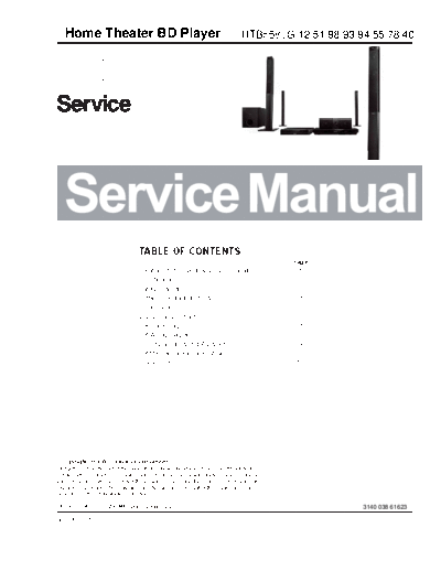
Service Manuals, User Guides, Schematic Diagrams or docs for : Philips Audio HTB5580G HTB5580G12_SB-EX-SI_1424956313
<< Back | HomeMost service manuals and schematics are PDF files, so You will need Adobre Acrobat Reader to view : Acrobat Download Some of the files are DjVu format. Readers and resources available here : DjVu Resources
For the compressed files, most common are zip and rar. Please, extract files with Your favorite compression software ( WinZip, WinRAR ... ) before viewing. If a document has multiple parts, You should download all, before extracting.
Good luck. Repair on Your own risk. Make sure You know what You are doing.
Image preview - the first page of the document

>> Download HTB5580G12_SB-EX-SI_1424956313 documenatation <<
Text preview - extract from the document
   Home Theater BD Player                                                                  HTB5580G/12/51/98/93/94/55/78/40


                                      TABLE OF CONTENTS
                                                                                                                          Page
                                      Location of PC Boards & Versions Variation ........................ 1
                                      Specifications ....................................................................... 2
                                      Safety Instruction .................................................................. 3
                                      Software Upgrade Instruction..................................................4
                                      Troubleshooting.................................................................... 5
                                      Disassembly Instructions ..................................................... 6
                                      Set Block Diagram ................................................................ 7
                                      Set Wiring Diagram .............................................................. 8
                                      Circuit Diagram & PCBA Layout........................................... 9
                                      Set Mechanical Exploded View ..........................................10
                                      Revision List ........................................................................ 11


Published by Niki & Lynn WK1444 Subject to modification                                                                           3140 038 61623

Version 1.5
                                            1-1


          PCBA Locations of Main Unit:


FRONT CONTROL BOARD                                                    LOADER


POWER BOARD
                                                                       MAIN BOARD
AMPLIFIER BOARD


        VERSION VARIATIONS
                       Type / Versions                     HTB5580

        Board in used   Service Policy     G/12 G/51 /98   /93   /94   /55   /78   /40
        MAIN BOARD                          M     M   M    M     M     M     M     M
        POWER BOARD                         C     C   C    C     C     C     C     C
        AMPLIFIER BOARD                     C     C   C    C     C     C     C     C
        FRONT CONTROL BOARD                 C     C   C    C     C     C     C     C
        TOUCH BOARD                         M     M   M    M     M     M     M     M
        NFC BOARD                           M     M   M    M     M     M     M     M
        LOADER                               M    M    M    M    M   M       M     M
        Tips                             C -- Component Lever Repair
                                           M -- Module Lever Repair
                                        1-2


       PCB Board Locations of Wireless Box


LED BOARD


                                                                   AMPLIFIER BOARD
POWER BOARD


     VERSION VARIATIONS OF WIRELESS BOX

                      Type / Versions                    HTB5580

      Board in used   Service Policy     G/12 G/51 /98   /93   /94   /55   /78   /40
     POWER BOARD                          M    M    M    M     M     M     M     M
     AMPLIFIER BOARD                      M    M    M    M     M     M     M     M
     LED BOARD                             M    M    M    M    M   M       M     M
     Tips                              C -- Component Lever Repair
                                         M -- Module Lever Repair
                                                                                     2-1


GENERAL DESCRIPTION
Home Theater BD DVD with Tuner,AUX,MP3,MIC,HDMI OUT,Optical,Coaxial,ARC,RJ45.

HTB3XXX&HTB5XXX 6*166W(10%) 3ohm For Power Amplifier,VFD Display,Aux in AudioIN,MIC
in,FM,USB,HDMI(ARC),OpticalIN,BT,Remote control


LIFETIME :     Years


  Class            Tuner             Supply + Amplifier                    USB                         Recorder               Clock       CD-mp3

     I              N/A                      N/A                            N/A                          N/A                  N/A              N/A
    II              Y                          Y                             Y
    III
   Page                9                       3-6
SAFETY requirements
Version                     Safety                                          EMC                                   EMC for LAN Network (RJ45)
                                                        EN55013:2001+A1:2003+A2:2006EN61000-3-
                                                        2:2006+A1:2009+A2:2009EN61000-3-3:2008,EN
                                                        55020:2007(IEC6100-4-2:2008IEC 6100-4-
          IEC60065:2001+A1:2005+A22010                  3:2008IEC6100-4-4:2004+Cor 1:2006+Cor
          EN 60065:2002 + A1:2006                       2:2007)
  CE      +A11:2008+A2:2010+A12:2012
  3C      GB8898-20119                                  GB13837-2003(IEC/CISPR13:2001,MOD)
Safety and EMC will be in accordance with the latest standards.

RADIATION / IMMUNITY

CLIMATIC requirements
ALL climates                         : + 0 Dregree           till             + 40 Degree
MODERATE climates                    : + N.A                 till             N.A Degree
PERFORMANCE CLASSES

POWER SUPPLY
MAINS ( A.C. )                               96-264V                 196~264V               196-310V              96-132V
Version                                  /55,77,/78/98,        /12,/40,/51,/79,/93            /94                   /F7
Frequency                                    50/60Hz                  50/60Hz               50/60Hz               50/60Hz


POWER CONSUMER
                                                     HTB35x0&HTB55x0 Versio
Stadby(Normal) :                                             < 0.5W
Stand By(Fast wake up):                                      <7.5W
( DEMO mode " OFF " ) , NOM. A, INPUT
Maximum :
@ 1/8 Prated , NOM. A, INPUT                                   N/A
ECO Power mode :                                               N/A


                       Quality          :      % ( Major )          % ( Mirror )
                       Reliability       :     % ( C 42 )
Tested according to General Test Instruction refer to PHILIPS standary
Measured according to PHILIPS standary ( UAN - L1059 ) unless other wise stated
All not mentioned date, please refer to PHILIPS standary ( XUW - 0010 - JUNE 2001 )
                   DERIVED                                              REMARKS                                     APPROBATION


Remarks
                                                                                  2-2

TECHNIAL DESCRIPTION
HTB3XXX&HTB5XXX/12 Total power 1000W(THD10%), matching SPEAKER of 6x 3Ohm
INPUT SOURCE: BD/DVD/CD/OPTICAL/ARC/TUNER/AUX /USB/MP3//COAXIAL


GENERAL PART
OUTPUT stage Protection              : Yes          Temperature          : Yes.               Short circuit      : Yes
LoudSpeaker D.C. Protection           : No

INDICATORS
Standby Mode Indicator        :LED(RED) Display
ECO Mode Indicator            : No


ELECTRICAL DATA
                                                                                                                                            Limit       Unit
Smart sound TBC                                                         Channel Difference at -40dB                                          3           dB

    MAX         N/A                                                     Hum ( Volume Minimum to max -20dB ) ( Except MIC )                  <200        nW


                N/A                                                     Hum ( For MIC only )                                                <200        nW

                                                                                                                                            <40
     IS :       N/A                                                     Residual Noise ( Volume Minimum )                                               nW

    VAC :       N/A                                                     Channel Separation ( at 1 kHz ) ( Except MP3 )                      60           dB

                                                                        Channel Separation ( at 1 kHz ) ( For MP3 only)                     55           dB

    VAC :       N/A                                                     Signal / Noise ( Except MIC )                                        60          dB


                                                                        Signal / Noise ( For MIC only )                                     55           dB
INTERCONNECTS

Input Sensitity(
◦ Jabse Service Manual Search 2024 ◦ Jabse Pravopis ◦ onTap.bg ◦ Other service manual resources online : Fixya ◦ eServiceinfo