Service Manuals, User Guides, Schematic Diagrams or docs for : Philips Audio LBB1229 SQ20_ET-SB-SI_1314768375
<< Back | HomeMost service manuals and schematics are PDF files, so You will need Adobre Acrobat Reader to view : Acrobat Download Some of the files are DjVu format. Readers and resources available here : DjVu Resources
For the compressed files, most common are zip and rar. Please, extract files with Your favorite compression software ( WinZip, WinRAR ... ) before viewing. If a document has multiple parts, You should download all, before extracting.
Good luck. Repair on Your own risk. Make sure You know what You are doing.
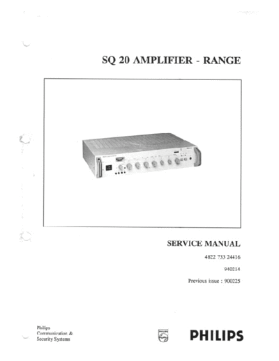
Image preview - the first page of the document
>> Download SQ20_ET-SB-SI_1314768375 documenatation <<
Text preview - extract from the document
Philips Communication & Security Systems
Supply Centre Breda
Customer Support
The Netherlands


COPYRIGHT (c) Philips Electronics N.V. 1994
Printed in the Netherlands
 Supply Centre Breda                                           SQ 20 Amplifiers


                                        CONTENTS

CHAPTER        DESCRIPTION                                              PAGE

1              INTRODUCTION                                                  3
1.1            GENERAL                                                       3
1.2            THE SQ20 RANGE                                                3
2              TECHNICAL DATA                                                4
3              INSTALLATION INSTRUCTIONS                                     4
4              CHECKING AND ADJUSTING                                        5
5              CIRCUIT DESCRIPTION                                           6
5.1            DIFFERENCE BETWEEN THE SEVERAL OUTPUT-STAGE'S                 6
6              SPARE PARTS                                                   7
6.1            RECOMMENDED SPARE-PARTS TOTAL SQ 20 SERIES                    8
6.2            SPARE-PARTS, LISTED PER TYPE-NUMBERS                          9
6.2.1          LBB 1227/00                                                   9
6.2.2          LBB 1228/00                                                   9
6.2.3          LBB 1229/00                                                  10
6.2.4          LBB 1230/00                                                  11
6.2.5          LBB 1231/00                                                  12
6.2.6          LBB 1232/00                                                  13
6.2.7          LBB 1233/00                                                  14
6.2.8          LBB 1234/00                                                  15
6.2.9          LBB 1235/00                                                  16
6.2.10         LBB 1236/00                                                  17
6.2.11         LBB 1237/00                                                  18
6.2.12         LBB 1238/00                                                  19
6.2.13         LBB 1240/00                                                  20


 Service documentation 4822 733 24416                          14 February 1994

                                         -1-
 SQ 20 Amplifiers                                                    Supply Centre Breda


                                        CONTENTS (cont'd)
7               DRAWINGS
                FIGURE: (as appendix)


7.1             LBB 1229/00 WIRING-DIAGRAM
7.2             LBB 1229/00 CIRCUIT-DIAGRAM PART 1
7.3             LBB 1229/00 CIRCUIT-DIAGRAM PART 2
7.4             LBB 1229/00 PRINTED CIRCUIT BOARD LAY-OUT

7.4.1           LBB 1230/00 CIRCUIT DIAGRAM PART 1
7.5             LBB 1230/00 CIRCUIT DIAGRAM PART 2
7.6             LBB 1230/00 PRINTED CIRCUIT BOARD LAY-OUT PART 1
7.7             LBB 1230/00 PRINTED CIRCUIT BOARD LAY-OUT PART 2

7.8             LBB 1231/00, -1232/00, -1233/00 CIRCUIT DIAGRAM PART 1
7.9             LBB 1231/00, -1232/00, -1233/00 CIRCUIT DIAGRAM PART 2
7.10            LBB 1231/00, LBB 1232/00, LBB 1233/00 PCB LAY-OUT PART 1
7.11            LBB 1231/00, LBB 1232/00, LBB 1233/00 PCB LAY-OUT PART 2

7.12            LBB 1234/00, LBB 1235/00 CIRCUIT DIAGRAM
7.13            LBB 1234/00, LBB 1235/00 PCB LAY-OUT

7.14            LBB 1237/00, LBB 1238/00 CIRCUIT DIAGRAM PART 1
7.15            LBB 1237/00, LBB 1238/00 CIRCUIT DIAGRAM PART 2
7.16            LBB 1237/00, LBB 1238/00 CIRCUIT DIAGRAM PART 3
7.17            LBB 1237/00, LBB 1238/00 CIRCUIT DIAGRAM PART 4
7.18            LBB 1237/00, LBB 1238/00 CIRCUIT DIAGRAM PART 5
7.19            LBB 1237/00, LBB 1238/00 PCB LAY-OUT PART 1
7.20            LBB 1237/00, LBB 1238/00 PCB LAY-OUT PART 2
7.21            LBB 1237/00, LBB 1238/00 PCB LAY-OUT PART 3

8.              ADDITIONAL TYPE NUMBERS (SERVICE INFORMATION)

8.1             LBB 1227/00 UNIVERSAL PRE-AMPLIFIER
8.2             LBB 1228/00 CASSETTE UNIT
8.3             LBB 1236/00 SYSTEM PRE-AMPLIFIER
8.4             LBB 1240/00 240 W BOOSTER AMPLIFIER

9.              GENERAL SERVICE INFORMATIONS


 SERVICE DOCUMENTATION 4822 733 24416                                  14 February 1994

                                             -2-
 Supply Centre Breda                                                                            SQ 20 Amplifiers


1        INTRODUCTION
l.l.     GENERAL
         The SQ20 range of high performance audio mixing, pre-mixing, booster and system amplifiers have been
         designed for use in a wide variety of Public Address environments. Ease of operation, combined with good
         service-accessibility have been optimised in their design.

1.2.     THE SQ 20 RANGE
         The SQ20 range consists of the following products:

         LBB 1227/00             Universal Pre-Amplifier                           : SI 4822 861 05025
         LBB 1228/00             Cassette Unit                                     : SI 4822 861 05012
         LBB 1229/00             Tuner-unit                                        : SM 4822 733 24416
         LBB 1230/00             Pre-Mixing Amplifier                              :: "           "
         LBB 1231/00             30 Watt Mixing Amplifier                          :: "           "
         LBB 1232/00             60 Watt Mixing Amplifier                          :: "           "
         LBB 1233/00             120 Watt Mixing Amplifier                         :: "           "
         LBB 1234/00             60 Watt Booster Amplifier                         :: "           "
         LBB 1235/00             120 Watt Booster Amplifier                        :: "           "
         LBB 1236/00             System Pre-Amplifier                              : SI 4822 861 05019
         LBB 1237/00             60 Watt System Amplifier                          : SM 4822 733 24416
         LBB 1238/00             120 Watt System Amplifier                         :: "           "
         LBB 1239/00             Mounting-brackets                                 : "          "
         LBB 1240/00             240 Watt Booster Amplifier                        : SI 4822 861 05039

         Note: SM -> Service manual
               SI -> Service information

         All relevant service information for the products can be found in the bulletins listed above. Not included
         in this manual are the callstation(s) LBB 9427/10, LBB 9527/10 and LBB 9527/60. The LBB 9427/10,
         and the new colour-item LBB 9527/10, are described within service manual: 4822 733 24437.
         The LBB 9527/60 is described within a service information: 4822 861 05002.

         This Service Manual is intended to provide all necessary information to carry out corrective maintenance
         according to agreed policies. Spare parts are defined accordingly. In general this means repair on sub
         assembly level. Component level repair can only be allowed where it can be carried out on a cost-effective
         way.


 Service documentation 4822 733 24416                                                           14 February 1994

                                                    -3-
SQ 20 Amplifiers                                                                             Supply Centre Breda


2       TECHNICAL DATA
        Figure 2.1 upto and including 2.4 give all relevant data for SQ20 products.
        For products for which service information is released through SI's this information can be found in
        chapter 8.

3       INSTALLATION INSTRUCTIONS
        -   Opening the amplifier

        Access can be gained to the inner side of the amplifier by removing the top cover.
        Care should be taken not to lose the toothed washers which are fitted underneath the screws. For safety
        reasons these washers are required to electrically bond the top cover to the earthed chassis of the amplifier.
        And must therefore always be fitted.

        Warning !:         Before removing the cover, disconnect the amplifier from the mains supply by
                           removing the mains plug!

        -   19" Rack Mounting

        The range of SQ20 system amplifiers have been designed for both tabletop and 19" rack mounting. Two
        mounting brackets (LBB 1239/00) can be ordered when rack mounting is required.

        To attach the mounting brackets, first remove the top cover as described.
        Locate the two screw holes provided for at both sides of the amplifier. Using the also added screws, firmly
        mount the brackets to the amplifier.

        CAUTION !:         SQ20 amplifiers are not suitable for any surveillance application with e.g. 20kHz.

                           It is essential that the SQ 20 products are used within the specified temperature range.
                           The maximum permissible temperature is + 45
◦ Jabse Service Manual Search 2026 ◦ Jabse Pravopis ◦ onTap.bg ◦ Other service manual resources online : Fixya ◦ eServiceinfo