Service Manuals, User Guides, Schematic Diagrams or docs for : Philips Audio MC-220 service
<< Back | HomeMost service manuals and schematics are PDF files, so You will need Adobre Acrobat Reader to view : Acrobat Download Some of the files are DjVu format. Readers and resources available here : DjVu Resources
For the compressed files, most common are zip and rar. Please, extract files with Your favorite compression software ( WinZip, WinRAR ... ) before viewing. If a document has multiple parts, You should download all, before extracting.
Good luck. Repair on Your own risk. Make sure You know what You are doing.
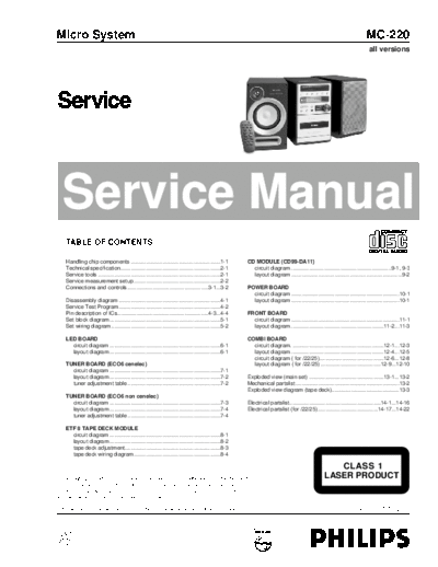
Image preview - the first page of the document

>> Download service documenatation <<
Text preview - extract from the document
Micro System                                                                                                                                                                        MC-220
                                                                                                                                                                                     all versions


  Service Manual
    TABLE OF CONTENTS

    Handling chip components ............................................................1-1                   CD MODULE (CD99-DA11)
    Technical specification...................................................................2-1                circuit diagram ...................................................................9-1, 9-3
    Service tools ..................................................................................2-1          layout diagram ..........................................................................9-2
    Service measurement setup ..........................................................2-2
    Connections and controls ......................................................3-1...3-2                   POWER BOARD
                                                                                                                 circuit diagram ........................................................................10-1
    Disassembly diagram ....................................................................4-1                  layout diagram ........................................................................10-1
    Service Test Program ....................................................................4-2
    Pin description of ICs.............................................................4-3...4-4               FRONT BOARD
    Set block diagram ..........................................................................5-1              circuit diagram ........................................................................11-1
    Set wiring diagram .........................................................................5-2              layout diagram ..............................................................11-2...11-3

    LED BOARD                                                                                                  COMBI BOARD
      circuit diagram ..........................................................................6-1              circuit diagram. .............................................................12-1...12-3
      layout diagram ..........................................................................6-1               layout diagram ..............................................................12-4...12-5
                                                                                                                 circuit diagram ( for /22/25)...........................................12-6...12-8
    TUNER BOARD (ECO6 cenelec)                                                                                   layout diagram ( for /22/25) ........................................12-9...12-10
      circuit diagram ..........................................................................7-1
      layout diagram ..........................................................................7-2             Exploded view (main set) ..................................................13-1...13-2
      tuner adjustment table ..............................................................7-2                 Mechanical partslist .....................................................................13-2
                                                                                                               Exploded view diagram (tape deck).............................................13-3
    TUNER BOARD (ECO6 non cenelec)
      circuit diagram ..........................................................................7-3            Electrical partslist.............................................................14-1...14-16
      layout diagram ..........................................................................7-4             Electrical partslist (for /22/25) ........................................14-17...14-22
      tuner adjustment table ..............................................................7-4

    ETF 8 TAPE DECK MODULE
      circuit diagram ..........................................................................8-1
      layout diagram ..........................................................................8-2
      tape deck adjustment................................................................8-3
      tape deck wiring diagram..........................................................8-4

                                                                                                                                                              CLASS 1
◦ Jabse Service Manual Search 2024 ◦ Jabse Pravopis ◦ onTap.bg ◦ Other service manual resources online : Fixya ◦ eServiceinfo