Service Manuals, User Guides, Schematic Diagrams or docs for : Philips LCD TV (and TPV schematics) VES16.1E la VES16.1E la
<< Back | HomeMost service manuals and schematics are PDF files, so You will need Adobre Acrobat Reader to view : Acrobat Download Some of the files are DjVu format. Readers and resources available here : DjVu Resources
For the compressed files, most common are zip and rar. Please, extract files with Your favorite compression software ( WinZip, WinRAR ... ) before viewing. If a document has multiple parts, You should download all, before extracting.
Good luck. Repair on Your own risk. Make sure You know what You are doing.
Image preview - the first page of the document
>> Download VES16.1E la documenatation <<
Text preview - extract from the document
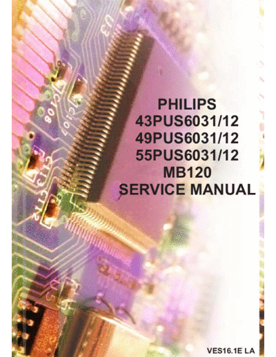
     PHILIPS
  43PUS6031/12
  49PUS6031/12
  55PUS6031/12
     MB120
SERVICE MANUAL


         VES16.1E LA
Table of Contents
1.        INTRODUCTION .......................................................................................................................................................... 2
2.        TUNER ........................................................................................................................................................................... 3
     A.       SI2151 Terrestrial and Cable TV Tuner: ..................................................................................................................... 3
     B.       M88TS2022 Satellite Tuner ........................................................................................................................................ 5
3.        AUDIO AMPLIFIER STAGES...................................................................................................................................... 6
     A.       MAIN AMPLIFIER (U8) (10W/12W options) ............................................................................................................... 6
     B.       SUBWOOFER AMPLIFIER (U9) (12 W) ........................................................................................................................ 8
     C.       HEADPHONE AMPLIFIER (U59) ................................................................................................................................ 10
     D.       SUBWOOFER PREAMPLIFIER (U30) .......................................................................................................................... 12
     E.       SCART AUDIO AMPLIFIER (U31) ............................................................................................................................... 12
4.        POWER STAGE ........................................................................................................................................................... 12
     A.       TPS54528 ................................................................................................................................................................. 13
     B.       TPS54628 ................................................................................................................................................................. 15
     C.       TPS54821 ................................................................................................................................................................. 17
     D.       FDS4685 ................................................................................................................................................................... 19
     E.       NTGS3446 ................................................................................................................................................................ 20
     F.       APL5910 ................................................................................................................................................................... 21
     G.       LM1117 .................................................................................................................................................................... 23
5.        MICROCONTROLLER (MSTAR MSD95M0D) ........................................................................................................ 24
6.        VIDEO BACK-END PROCESSOR (MSTAR) ........................................................................................................... 31
7.        2Gb DDR3 SDRAM ..................................................................................................................................................... 34
8.        4Gb DDR3L SDRAM ................................................................................................................................................... 35
9.        32GBIT (4G X 8 BIT) NAND FLASH MEMORY ..................................................................................................... 37
10. 16M-BIT [16M x 1] CMOS SERIAL FLASH EEPROM ............................................................................................ 39
     A.       MX25L1606E SPI Flash ............................................................................................................................................. 39
     B.       M25Q32FV SPI Flash ................................................................................................................................................ 41
11. DEMODULATOR STAGE .......................................................................................................................................... 43
12. LNB SUPPLY AND CONTROL IC ............................................................................................................................ 46
13. SERVICE MENU SETTINGS ..................................................................................................................................... 48
     A.       Video Settings .......................................................................................................................................................... 48
     B.       Audio Settings .......................................................................................................................................................... 49
     C.       Options ..................................................................................................................................................................... 49
     D.       Tuning Settings......................................................................................................................................................... 51
     E.       Source Settings ........................................................................................................................................................ 51
     F.       Diagnostic................................................................................................................................................................. 52

1
    G.     USB Operations ........................................................................................................................................................ 52
14. SOFTWARE UPDATE ................................................................................................................................................ 52
15. HI-POT TEST ............................................................................................................................................................... 52
16. MECHANICAL INSTRUCTIONS .............................................................................................................................. 53
17. TROUBLESHOOTING ................................................................................................................................................ 56
18. PCB LAYOUTS ........................................................................................................................................................... 68
19. PARTS POSITIONS ..................................................................................................................................................... 72
20. MAPPING DATA......................................................................................................................................................... 73
21. GENERAL BLOCK DIAGRAM ................................................................................................................................. 74
22. STYLING SHEETS ...................................................................................................................................................... 75
23. SPARE PART LISTS ................................................................................................................................................... 76


    1. INTRODUCTION
   17MB120 main board is driven by MStar SOC. This IC is a single chip iDTV solution that supports channel
decoding, MPEG decoding, and media-center functionality enabled by a high performance AV CODEC and
CPU. This IC also supports 4K2K (UHD).

Key features includes,

           Combo Front-End Demodulator
           A multi standart A/V format decoder
           The MACEpro video processor
           Home theatre sound processor
           Internet and Variety of Connectivity Support
           Dual-stream decoder for 3D contents
           Multi-purpose CPU for OS and multimedia
           Peripheral and power management

Supported peripherals are:

           1 RF input VHF I, VHF III, UHF
           1 Satellite input
           1 Side AV (CVBS, R/L_Audio)
           1 SCART socket(Common)
           1 YPbPr / Back S-Video(Common)
           1 PC input(Common)
           4 HDMI input(Common)
           1 Common interface(Common)
           1 Optic S/PDIF output(Common)
           1 Stereo audio input for PC(Common)
           1 Subwoofer output(Common)
           1 Headphone(Common)
           1x USB3.0 and 2xUSB2.0(Common)
           1 Ethernet-RJ45 (Common)
           1 External Touchpad(Common)


2
    2. TUNER
    A. SI2151 TERRESTRAL AND CABLE TV TUNER:
Description:
   The Si2151 is Silicon Labs' sixth-generation hybrid TV tuner supporting all worldwide terrestrial and cable
TV standards. Requiring no external balun, SAW filters, wirewound inductors or LNAs, the Si2151 offers the
lowest-cost BOM for a hybrid TV tuner. Also included are an integrated power-on reset circuit and an option
for single power supply operation. As with prior-generation Silicon Labs TV tuners, the Si2151 maintains very
high linearity and low noise to deliver superior picture quality and a higher number of received stations when
compared to other silicon tuners. The Si2151 offers increased immunity to WiFi and LTE interference,
eliminating the need for external filtering. For the best performance with next-generation digital TV standards,
such as DVB-T2/C2, the Si2151 delivers industry-leading phase noise performance.
Features:
 Worldwide hybrid TV tuner
          o Analog TV: NTSC, PAL/SECAM
          o Digital TV: ATSC/QAM, DVBT2/T/C2/C, ISDB-T/C, DTMB
 1.7 MHz, 6 MHz, 7 MHz, 8 MHz, and 10 MHz channel bandwidths
 42-1002 MHz frequency range
 Industry-leading margin to A/74, NorDig, DTG, ARIB, EN55020, OpenCableTM,DTMB
 Lowest BOM for a hybrid TV tuner
          o No balun, SAW filters, or external inductors required
          o Increased ESD protection on 4pins
 Best-in-class real-world reception
          o Lowest phase noise
          o High Wi-Fi and LTE immunity
 Low power consumption
          o 3.3 V and 1.8 V power supplies
          o Integrated 1.8 V LDO for 3.3 V singlesupply operation
 Integrated power-on reset circuit
 Standard CMOS process
 3x3 mm, 24-pin QFN package
 RoHS compliant


                                       Figure 1.1 Si2151 Pin description


3
    Table 1.1 Pin Functions


4
    B. M88TS2022 SATELLTE TUNER
Features and General Description


Pin Assigment


5
Absolute Maximum Ratings and Recommended Operating Conditions


    3. AUDIO AMPLIFIER STAGES
    A. MAIN AMPLIFIER (U8) (10W/12W OPTONS)
Description
   AD82587D is a digital audio amplifier capable of driving a pair of 8 ohm, 20W or a single 4 ohm, 40W
speaker, both which operate with play music at a 24V supply without external heat-sink or fan requirement.
   Using I2C digital control interface, the user can control AD82587D's input format selection, DRC (dynamic
range control), mute and volume control functions. AD82587D has many built-in protection circuits to
safeguard AD82587D from connection errors.
Features
 16/18/20/24-bit input with I2S, Left-alignment and Right-alignment data format
 PSNR & DR(A-weighting) Loudspeaker: 97dB (PSNR), 105dB (DR) @ 24V
 Multiple sampling frequencies (Fs)
          32kHz / 44.1kHz / 48kHz and
          64kHz / 88.2kHz / 96kHz and
          128kHz/176.4kHz/192kHz
 System clock = 64x, 128x, 256x, 384x, 512x, 768x,1024x Fs
          256x~1024x Fs for 32kHz / 44.1kHz / 48kHz
          128x~512x Fs for 64kHz / 88.2kHz / 96kHz
          64x~256x Fs for 128kHz /176.4kHz/192kHz
 Supply voltage
          3.3V for digital circuit
          10V~26V for loudspeaker driver
6
    Loudspeaker output power for Stereo@ 24V
             10W x 2ch into 8_ @ 0.16% THD+N
             15W x 2ch into 8_ @ 0.18% THD+N
             20W x 2ch into 8_ @ 0.24% THD+N
    Loudspeaker output power for Mono@ 24V
             20W x 1ch into 4_ @ 0.17% THD+N
             30W x 1ch into 4_ @ 0.2% THD+N
             40W x 1ch into 4_ @ 0.24% THD+N
    Sounds processing including:
             Volume control (+24dB~-103dB, 0.125dB/step)
             Dynamic range control
             Power clipping
             Channel mixing
             User programmed noise gate with hysteresis window
             DC-blocking high-pass filter
    Anti-pop design
    Short circuit and over-temperature protection
    I2C control interface with selectable device address
    Internal PLL
    LV Under-voltage shutdown and HV Under-voltage
    detection
    Power saving mode
    Dynamic temperature control


                                       Figure 3.2: Pin description


7
                                    Figure 3.3: Functional Block Diagram


                                    Table3.1: Absolute Maximum Ratings


                                Table3.2: Recommended Operating Conditions

    B. SUBWOOFER AMPLIFIER (U9) (12 W)
Description
   AD82586C is a digital audio amplifier capable of driving a pair of 8 ohm, 20W operating at 24V supply
without external heat-sink or fan requirement with play music.

    AD82586C has 20 bands EQ function and can operate 20W stereo or 40W mono optionally.

    AD82586C can provide advanced audio processing capabilities, such as volume control, 20 bands speaker
EQ, audio mixing, 3D surround and DRC (dynamic range control). These functions are fully programmable via
a simple I2C control interface.

    Robust protection circuits are provided to protect AD82586C from damage due to accidental erroneous
operating condition. AD82586C is more tolerant to noise and PVT (Process, Voltage, and Temperature)
variation than the analog Class-AB or Class-D audio amplifier counterpart implemented by analog circuit
design. AD82586C is pop free during instantaneous power switch because of its built-in, robust anti-pop circuit.
8
Features
 16/18/20/24-bits input with I2S, Left-alingment and Right-alingment data format
 PSNR & DR (A-weighting) Loudspeaker: 99dB (PSNR), 104dB (DR) @24V
 Multiple sampling frequencies (Fs)
      32kHz / 44.1kHz / 48kHz and
      64kHz / 88.2kHz / 96kHz and
      128kHz / 176.4kHz / 192kHz
 System clock = 64x, 128x, 192x, 256x, 384x, 512x, 576x, 768x, 1024x Fs
      64x~1024x Fs for 32kHz / 44.1kHz / 48kHz
      64x~512x Fs for 64kHz / 88.2kHz / 96kHz
      64x~256x Fs for 128kHz / 176.4kHz / 192kHz
 Supply voltage
      3.3V for digital circuit
      10V~26V for loudspeaker driver
 Loudspeaker output power at 24V
      10W x 2CH into 8 ohm @0.17% THD+N for stereo
      20W x 2CH into 8 ohm @0.26% THD+N for stereo
 Sound processing including:
      20 bands parametric speaker EQ
      Volume control (+24dB~-103dB, 0.125dB/step)
      Dynamic Range Control (DRC)
      Dual band DRC
      Power clipping
      3D surround sound
      Channel mixing
      Noise gate with hysteresis window
      Bass/Treble tone control
      DC-blocking high-pass filter
 Anti-pop design
 Short circuit and over-temperature protection
 I2C control interface with selectable device address
 Support hardware and software reset
 Internal PLL
 LV Under-Voltage shutdown and HV Under-Voltage detection
 Power saving mode


                                        Figure 3.4: Pin description
9
                                   Figure 3.5: Functional Block Diagram


                                   Table 3.3: Absolute Maximum Ratings


                              Table 3.4: Recommended Operating Conditions

     C. HEADPHONE AMPLIFIER (U59)
Description
   The AD22657B is a 2-Vrms cap-less stereo line driver. The device is ideal for single supply electronics.
Cap-less design can eliminate output dc-blocking capacitors for better low frequency response and save cost.

    The AD22657B is capable of delivering 2-Vrms output into a 10k ohm load with 3.3V supply. The gain
settings can be set by users from 1V/V to 10V/V externally. The AD22657B has under voltage protection to
prevent POP noise. Build-in shutdown control and de-pop control sequence also help AD22657B to be a pop-
less device.

     The AD22657B is available in a 10-pin MSOP package.
Features
 Operation Voltage: 3V to 3.6V
 Cap-less Output
          Eliminates Output Capacitors
          Improves Low Frequency Response
          Reduces POP/Clicks
 Low Noise and THD

10
              Typical SNR 107dB
              Typical Vn 7uVrms
              Typical THD+N < 0.02%
     Maximum Output Voltage Swing into 2.5k Load
              2Vrms at 3.3V Supply Voltage
     Single-ended Input
     External Gain Setting from 1V/V to 10V/V
     Fast Start-up Time: 0.5ms
     Integrated De-Pop Control
     External Under Voltage Protection
     Thermal Protection
     Less External Components Required
     +/-8kV IEC ESD Protection at line outputs


                                       Figure 3.6: Pin description


                                        Table 3.5: Pin functions


                              Table3.6: Recommended operating conditions


11
     D. SUBWOOFER PREAMPLIFIER (U30)
     AD22657B is used for subwoofer out, as well.


     E. SCART AUDIO AMPLIFIER (U31)
     AD22657B is used for scart audio amplifier, as well.


 4. POWER STAGE


                                     Figure 4.1: Power socket and options.

   Power socket is used for taking voltages which are 12V, 5V and VDD_Audio. These voltages are produced
in power board. Also socket is used for giving dimming, backlight and standby signals with power board. It is
shown at figure 4.1.


12
                       Figure 4.2: General illustration of voltage stages on main board.

   VDD_Audio goes directly to the audio side, through power socket other incoming voltages from power card
are converted several voltages, shown in figure 8.

List of the components are:
 TPS54528
 TPS54628
 TPS54821
 FDS4685
 NTGS3446
 APL5910
 LM1117

     A. TPS54528
General Description
   The TPS54528 is an adaptive on-time D-CAP2 mode synchronous buck converter.The TPS54528 enables
system designers to complete the suite of various end-equipment power bus regulators with a cost effective, low
component count, low standby current solution. The main control loop for the TPS54528 uses the D-CAP2
mode control that provides a fast transient response with no external compensation components. The adaptive
on-time control supports seamless transition between PWM mode at higher load conditions and Eco-mode
operation at light loads. Eco-mode allows the TSP54528 to maintain high efficiency during lighter load
conditions. The TPS54528 also has a proprietary circuit that enables the device to adopt to both low equivalent
series resistance (ESR)output capacitors, such as POSCAP or SP-CAP, and ultra-low ESR ceramic capacitors.
The device operates from 4.5-V to 18-V VIN input. The output voltage can be programmed between 0.76 V
and 6 V. The device also features an adjustable soft start time. The TPS54528 is available in the 8-pin DDA
package, and designed to operate from -40 C to 85 C.

13
Features
 D-CAP2 Mode Enables Fast Transient Response
 Low Output ripple and Allows Ceramic Output Capacitor
 Wide VIN Input Voltage Range: 4.5 V to 18 V
 Output Voltage Range: 0.76 V to 6 V
 Highly Efficient Integrated FETs Optimized for Lower Duty Cycle Applications- 65 mOhm (High Side)
   and 36 mOhm (Low Side)
 High Efficiency, less than 10 mikroAmper at shutdown
 High Initial Bandgap Reference Accuracy
 Adjustable Soft Start
 Pre-Biased Soft Start
 650-kHz Switching Frequency (fSW)
 Cycle By Cycle Over Current Limit
 Auto-Skip Eco-mode for High Efficiency at Light Load


Applications
 Wide Range of Applications for Low Voltage System
 Digital TV Power Supply
 High Definition Blu-ray Disc Players
 Networking Home Terminal
 Digital Set Top Box(STB)


                            Table 4.1: Recommended operating conditions


                                     Figure 4.3: Pin Description


14
                                           Table 4.2: Pin functions.


     B. TPS54628
General Description
   The TPS54628 is an adaptive on-time D-CAP2 mode synchronous buck converter.The TPS54628 enables
system designers to complete the suite of various end-equipment power bus regulators with a cost effective, low
component count, low standby current solution. The main control loop for the TPS54628 uses the D-CAP2
mode control that provides a fast transient response with no external compensation components. The adaptive
on-time control supports seamless transition between PWM mode at higher load conditions and Eco-mode
operation at light loads. Eco-mode allows the TSP54628 to maintain high efficiency during lighter load
conditions. The TPS54628 also has a proprietary circuit that enables the device to adopt to both low equivalent
series resistance (ESR)output capacitors, such as POSCAP or SP-CAP, and ultra-low ESR ceramic capacitors.
The device operates from 4.5-V to 18-V VIN input. The output voltage can be programmed between 0.76 V
and 7 V. The device also features an adjustable soft start time. The TPS54628 is available in the 8-pin DDA and
10-pin DRC packages, and is designed to operate over the ambient temperature range of -40C to 85C.
Features
 D-CAP2 Mode Enables Fast Transient Response
 Low Output ripple and Allows Ceramic Output Capacitor
 Wide VIN Input Voltage Range: 4.5 V to 18 V
 Output Voltage Range: 0.76 V to 7 V
 Highly Efficient Integrated FETs Optimized for Lower Duty Cycle Applications- 36 mOhm (High Side)
   and 28 mOhm (Low Side)
 High Efficiency, less than 10
◦ Jabse Service Manual Search 2026 ◦ Jabse Pravopis ◦ onTap.bg ◦ Other service manual resources online : Fixya ◦ eServiceinfo