Service Manuals, User Guides, Schematic Diagrams or docs for : Philips Monitor 201P1 CHASSIS CM25PLUS philips_201p1_chassis_cm25plus
<< Back | HomeMost service manuals and schematics are PDF files, so You will need Adobre Acrobat Reader to view : Acrobat Download Some of the files are DjVu format. Readers and resources available here : DjVu Resources
For the compressed files, most common are zip and rar. Please, extract files with Your favorite compression software ( WinZip, WinRAR ... ) before viewing. If a document has multiple parts, You should download all, before extracting.
Good luck. Repair on Your own risk. Make sure You know what You are doing.
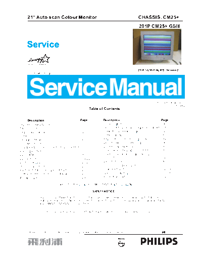
Image preview - the first page of the document

>> Download philips_201p1_chassis_cm25plus documenatation <<
Text preview - extract from the document
        21" Auto scan Colour Monitor                                                                                            CHASSIS: CM25+

       Service                                                                                                                   201P CM25+ GSIII

       Service
       Service

                                                                                                                                201P 10/00(PHILIPS)-Version 2
        DDC/Power saving/TCO


                                                                                                                                                   Horizontal frequencies
                                                                                                                                                             30 - 121kHz
                                                                              Table of Contents


        Description                                                  Page                     Description                                              Page
Important Safety Notice . . . . . . . . . . . . . . . . . . . ....2                           Block Diagram............................................. ...30
Technical Data. . . . . . . . . . . . . . . . . . . . . . . . . . . ....3                     Terminal(A1) Schematic Diagram & PCB (A1)...31
Regulatory Information. . . . . . . . . . . . . . . . . . . . ....4                           Video(A2) Schematic Diagram ........................32
Installation . . . . . . . . . . . . . . . . . . . . . . . . . . . . . . ....5                Video PCB (A2)..............................................33
Resolution Modes . . . . . . . . . . . . . . . . . . . . . . . . ....6                        Key Control Schematic Diagram & PCB (E)......34
OSD Adjustment . . . . . . . . . . . . . . . . . . . . . . . . . ....7~15                     Deflection(B) Schematic Diagram....................35
OSD Lock & Unlock,Service Mode,Burn In Mode.16                                                Deflection & Power PCB (B, C)........................36
Warning and Notes . . . . . . . . . . . . . . . . . . . . . . . ....17                        Power Schematic Diagram (C) & MHR (F)........37
DDC DATA . . . . . . . . . . . . . . . . . . . . . . . . . . . . . . ....18                   Driver(D) Schematic Diagram & PCB (D).........38
DDC Instructions. . . . . . . . . . . . . . . . . . . . . . . . . ....19~22                   Repair Tips ...................................................39
Electrical Adjustments . . . . . . . . . . . . . . . . . . . . ....23~25                      Exploded View...............................................40
Mechanical Instructions . . . . . . . . . . . . . . . . . . . ....26                          Recommended Parts List................................41
Purity and Static convergence Adjustments . . ....27                                          Spare Parts List..............................................42~49
Safety Test Requirements (Hipot & Ground) . . ....28                                          General Product Specification.........................50~81
Wiring Diagram . . . . . . . . . . . . . . . . . . . . . . . . . . ....29                     Repair flow chart.............................................82~89

                                           REFER TO BACK COVER FOR IMPORTANT SAFETY GUIDELINES

                                                                                   SAFETY NOTICE

                      ANY PERSON ATTEMPTING TO SERVICE THIS CHASSIS MUST FAMILIARIZE HIMSELF WITH THE CHASSIS
                      AND BE AWARE OF THE NECESSARY SAFETY PRECAUTIONS TO BE USED WHEN SERVICING ELECTRONIC
                      EQUIPMENT CONTAINING HIGH VOLTAGES.


                           CAUTION: USE A SEPARATE ISOLATION TRANSFORMER FOR THIS UNIT WHEN SERVICING.
◦ Jabse Service Manual Search 2024 ◦ Jabse Pravopis ◦ onTap.bg ◦ Other service manual resources online : Fixya ◦ eServiceinfo