Service Manuals, User Guides, Schematic Diagrams or docs for : Philips Monitor CD 2001 Monitor CD 2001 E-MANUALS Philips crt 105b2 105b2_pdf p23_25
<< Back | HomeMost service manuals and schematics are PDF files, so You will need Adobre Acrobat Reader to view : Acrobat Download Some of the files are DjVu format. Readers and resources available here : DjVu Resources
For the compressed files, most common are zip and rar. Please, extract files with Your favorite compression software ( WinZip, WinRAR ... ) before viewing. If a document has multiple parts, You should download all, before extracting.
Good luck. Repair on Your own risk. Make sure You know what You are doing.
Image preview - the first page of the document
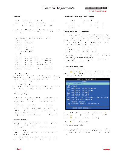
>> Download p23_25 documenatation <<
Text preview - extract from the document
Electrical Adjustments 105B2 CM23 GSIII 23
9 Go to cover page
0. General 3.Monitor the following auxiliary voltages.
When carry-out the electrical settings in many cases a video signal SOURCE ACROSS C2153 and GRN +183.0V +/- 1.5 VDC
must be applied to the monitor. A computer with : SOURCE ACROSS C2156 +81.0V +/- 0.5 VDC.
SOURCE ACROSS C2164 +6.2V +/- 0.3 VDC.
- ATI GPT-1600 (4822 397 10065), Mach 64 (up to 107kHz) SOURCE ACROSS C2158 +12.7V +/- 0.5 VDC.
SOURCE ACROSS C2162 - 12.7V +/- 0.5 VDC.
are used as the video signal source. The signal patterns are selected
from the "service test software" package, see user guide 4822 727 4. General conditions for alignment
21046 (GPT-1600).
4.1 During all alignments, supply a distortion free AC mains voltage
to set via an isolating transformer with low internal impedance.
0.1 This monitor has 8 factory-preset modes as below. 4.2 Align in pre-warmed condition, at least 30 minutes warm-up with
720 x 400 31.5 kHz/70 Hz nominal picture brightness.
640 x 480 31.47 kHz/60 Hz 4.3 Purity, geometry and subsequent alignments should be carried
640 x 480 43.3 kHz/85 Hz out in magnetic cage with correct magnetic field.
800 x 600 46.9 kHz/75 Hz
800 x 600 53.8 kHz/85 Hz Northern hemisphere : H=0, V=450 mG, Z=0
1024x768 60.0 kHz/75 Hz Southern hemisphere : H=0, V=-500 mG, Z=0
1280x1024 64.0kHz/60Hz Equatorial Support : H=0, V=0 mG, Z=0
1024x768 68.7kHz/85Hz
4.4 All voltages are to be measured or applied with respect to ground.
14 factory-preload modes as below Note: Do not use heatsink as ground.
640 x 350 31.5 kHz/70 Hz 800 x 600 48.1kHz/72Hz 4.5 Adjust brightness controls to center position except for contrast
640 x 350 37.9 kHz/85 Hz 800 x 600 63.9kHz/100Hz control which should be set to MAX.
640 x 480 37.5 kHz/75 Hz 832 x 624 49.7kHz/75Hz
640 x 480 37.9 kHz/73 Hz 1024x768 48.4kHz/60Hz
640 x 480 50.6kHz/100Hz 1024x768 56.5kHz/70Hz 5. To access factory mode:
720 x 400 37.9kHz/85Hz 1152x864 67.5kHz/75Hz
800 x 600 37.9kHz/60Hz 1280x960 60.0kHz/60Hz - Turn off monitor (don't turn off PC)
- Press " " and " " simultaneously on the front control panel
0.2 With normal VGA card: ,then press " ",wait till the OSD menu with characters
If not using the ATI card during repair or alignment, The service " factory mode (below OSD menu)" come on the screen of monitor.
engineer also can use this service test software adapting with normal
standard VGA adaptor and using standard VGA mode 640 x 480,
31.5 kHz/60 Hz (only) as signal source. 00562
0.3 AC/DC Measurement:
The measurements for AC waveform and DC figure is based on 640 x
480 31.5 kHz/60 Hz resolution mode with test pattern "gray scale".
Power input: 110V AC
1. B+ supply voltage
- Apply a video signal in the 640 x 480 with 31.5 kHz/60Hz mode.
- Select the "cross-hatch" pattern.
- Set the brightness control and the contrast control to the minimum
MODEL SELECT
position.
- Pre-set trimming potentiometer R3178(B+) and R3540 (EHT)
in mid-position.
- Set Vg2 (screen) to fully Counter-clockwise (zero beamcurrent). 105BS V2.37 20000510
- Connect a dc voltmeter between the joint of capacitor C2156 and
ground (common ground). - If OSD menu disappears on the screen of monitor, press " "
- Set the B+ trimming potentiometer R3178(B+) so that the reading again (anytime), then the OSD menu comes on the screen again.
on the dc voltmeter is 81V +/- 0.2 Vdc. - using " " : to select OSD menu.
- using " " : to increase or decrease the setting.
2. High-voltage EHT
- Using " " to confirm the selection.
- Apply a video signal in the 640 x480 with 31.5 kHz/60Hz mode.
- Select the "cross-hatch" pattern. 5.1. To leave factory mode
- Set the brightness control and the contrast control to the minimum
position. * After alignment of factory mode, turn off monitor (if you do not turn
- Turn off the power. off monitor, the OSD menu is always at the factory mode), then turn
- Connect a dc voltmeter between the joint of capacitor C2643 and on monitor again (at this moment, the OSD menu goes back to user
ground (common ground). mode).
- Turn on the power.
- Set the EHT trimming potentiometer R3540 so that the reading on
the dc voltmeter is 66.5V +/-0.2V for PHI CRT(67V for CPT CRT).
3Back Forward4
24 105B2 CM23 GSIII Electrical Adjustments (Continued)
9 Go to cover page
6. Picture geometry setting
9300 BIAS R G B GAIN R G B
- Apply a video signal with cross-hatch pattern. 6500 BIAS R G B GAIN R G B
6.2 Apply a video signal in the 1024 x 768 with 68.7 kHz/85 Hz mode. FOCUS(H V) VLIN BAL USER
6.3 Set contrast control at Max. position, and brightness control in RASTER(H V) LIN ( H V ) SUB
Fig. 2.2
the mid-point. SUB T CORNER ABL
6.4 Alignment of horizontal geometry and vertical geometry H EHT
6.4.1 Adjust the H-width to 270 mm VE (HILI SHARP)
6.4.2 Adjust the H-phase to center position. EXIT
174
6.4.3 Adjust V-size to 202mm.
6.4.4 Adjust V-Position to center.
Adjust/Trapezium/pincushion
6.4.5 Adjust picture tilt via I2C BUS for correct top/bottom lines. BIAS R G B : R(red) G(green) B(blue) cutoff
6.4.6 Adjust the top and bottom corner by I2C to straight vertical lines GAIN R G B : R(red) G(green) B(blue) gain
of the left and right edge. FOCUS : Horizontal and Vertical Focus
6.4.7 Adjust the parallelogram by I2 CBUS to get optimum vertical line. VLIN BAL : Vertical Linearity Balance
6.4.8 Adjust the unbalance pin by I2C BUS to get optimum vertical USER : Horizontal size range
line. RASTER H: Horizontal DC (raster) Shift
RASTER V: Vertical DC (raster) Shift
6.4.9 Adjust the unbalance Vertical linearity balance by I C BUS to
2
HLIN : Horizontal Linearity
get optimum vertical linearity balance.
V LIN : Vertical Linearity
6.4.10Adjust the unbalance Vertical linearity by I C to get optimum
2
SUB : Zoom range
vertical linearity.
SUB : Sub Contrast
6.5 Adjust size/centering/trapezium/pincushion/parallelogram
T CORNER: Corner Correctionof TOP
of all other preset modes via I C bus.
2
ABL : Auto Beam Limit
6.6 Preset factory preload timing according to step 6.5 values.
H EHT : Horizontal Extensive High Tension
VE : Intensity and sharpness of lightframe
7. Alignment of Vg2 cut-off point, white tracking
( the value must be under 5)
Equipment : 1. Video Test Generator-801GC (Quantum Data)
(Before you make an adjustment of VE s value of intensity or sharp.
2. Color-analyzer (Minolta CA-100) Please make sure the VE function has enable properly by entering
VG2 [(screen), at the bottom of the L.O.T.]. Model Select submenu that will show you it is active or not.) A red
* Apply a video signal in the 1024 x 768 with 60 kHz/75 Hz mode, square near by VE means function active. Refer to the Fig. As below.
select the "full white pattern" (sizes 270 x 202 mm).
* Use color-analyzer (Minolta CA-100) to adjust cutoff and MODEL SELECT
white uniformity.
105B2 69K TCO
OSD R/G/B cut-off and R/G/B gain can be accessed, with
initial data: 105B2 69K MPR2
105S2 60K TCO
9300 oK 105S2 60K MPR2
R cutoff = 25%, R gain = 65% (I2 C)
RESERVE
G cutoff = 25%, G gain = 65% (I C)
2
B cutoff = 25%, B gain = 65% (I C)
2
SWDDC
VE
6500 K
o
R cutoff = 25%, R gain = 55% (I C)
2
7.2 Connect the video input, set brightness control at center, and
G cutoff = 25%, G gain = 55% (I C)
2
contrast control at maximum
B cutoff = 25%, B gain = 55% (I C)
2
7.3
set R,G,B cut-off at 127 9300k and 6500K(EEPROM preload
Brightness = 50%, Sub-Contrast = 85%, ABL = 50% (I C)
2
value)
R,G,B gain at 77 9300k and 6500K(EEPROM preload
Step 1: To press power button switch and left & right value)
simulaneously to entert the character "105BS V2.37 ABL at 127 9300k and 6500K(EEPROM preload
20000510 " as shown in Fig.2.1, press " " to access the value)
OSD menu for R/G/B gain & cutoff as shown in Fig. 2.2. SUB-CON at 218 (EEPROM preload value)
Step 2: Press " " for function selection as shown in Fig. 2.2. 7.4 Adjust 9300K color:
With the help of a factory calibrated color analyzer CA 100
set low R,G,B scale 100=0.12FL,x=283,y=297
Adjust Vg2 until brightest gun at 100 on low brightness scale.
7.5 Adjust R,G,B cut-off for all gun reading to get 100 on low
brightness scale.
7.6 Set CA100 high R,G,B scale 100 = 41+/- 1FL,X=283,y=297
Adjust G gain at 100 scale on high brightness scale.
7.7 Adjust R,B gain so that blue and green have the same reading as
red on the high brightness scale
7.8 Set contrast at minimum and repeat 7.5,7.6,7.7,until RGB three
guns get same readings on low and high brightness scale.
7.8.1 Adjust SUB-CON to get Y=41+/- 1FL
MODEL SELECT 7.8.2 Apply full white pattern, Adjust ABL to reach 30+/- 1FL(contrast
at Max.)
7.9 Adjust 6500K color:
105BS V2.37 20000510 With the help of a factory calibrated color analyzer CA 100
set low R,G,B scale 100=0.12FL,x=313,y=329
3Back Forward4
Electrical Adjustments (Continued) 105B2 CM23 GSIII 25
9 Go to cover page
7.10 Adjust the R,G,B cut-off for all gun reading to get 100 on low - First set the 4-pole magnet optimally.
brightness scale. - Then set the 6-pole magnet optimally.
7.11 Set CA100 high R,G,B scale 100 = 41+/- 1FL,X=313,y=329 - If the convergence is not now optimal, then adjust to
Adjust G gain at 100 scale on high brightness scale. the optimal setting with the 4-pole magnet and then with
7.12 Adjust R,B gain so that blue and green have the same reading the 6- Pole magnet again.
as red on the high brightness scale - Set the tabs of the 6-pole magnet in the neutral
7.13 Set contrast at minimum and repeat 7.10,7.11,7.12,until RGB position. This is when the tabs are opposite one
three guns get same readings on low and high brightness another. In this position the magnets do not affect the
scale. deflection of the R, B, and G electron beams.
7.14 Check full white at contrast and brightness at minimum, the - First set the 4-pole magnet optimally.
foreground shall be extinguished. - Then set the 6-pole magnet optimally.
- If the convergence is not now optimal, then adjust to
the optimal setting with the 4-pole magnet and then
8. Focus adjustment with the 6- pole magnet again.
Apply a signal of " @ " character. at 68.7 kHz/85 Hz mode set the
brightness to mid-position , contrast to max - position and adjust
the focus for optimal sharpness in the area within 2/3 from the
screen center.
9. Loading DDC code
The DDC HEX data should be written into the EEPROM
(7803,7804) by EEPROM writer or equivalent method.
a: Service DDC Kit
DDC Module (DDC cable), Part number = 4822 320 12004
DDCV2u.EXE software (3.5" disk), Part number = 4822 711 00024
b: Please refer to Service information 4822 727 21995 for using
the Service DDC Kit.
10. Purity adjustment 2-pole purity magnet
6-pole convergence magnet
- Make sure the monitor is not exposed to any
4-pole convergence magnet
external magnetic field.
- Produce a full red pattern on the screen, adjust the
Deflection Yoke
purity magnet rings on the PCM assy (on CRT) to
obtain a complete field of the color red. This is done
by moving the two tabs (2-pole) in such a manner
4-pole Beam motion producced by the
that they advance in an opposite direction but at
the same time to obtain the same angle between 4-pole convergence magnet
the two tabs, which should be approximately 180
degree.
S
- Check by full green pattern and full blue pattern S N
again to observe their respective color purity.
B G R N B G R N
11. Static convergence
N S
Introduction S
Slight deviation in the static convergence can be
corrected by using two permanent pairs of magnets
which are fitted around the neck of the CRT. These Beam displacement Magnetic flux
are the 4-pole magnet and the 6-pole magnet. direction lines
The 4-pole magnet move the outermost electron
beams (R and B) parallel in the opposite direction
from the other. The 6-pole magnet moves the
outermost electron beam (R, B and G) parallel in the
opposite direction from the other. 6-pole Beam motion producced by the
The magnetic field of the above magnets do not affect 6- pole convergence magnet
the center of the CRT neck.
N
S N
Setting
S S
- Before the static convergence setting can be made,
the monitor must be switched on for 30 minutes. B G R N B G R S
- The focus setting must be made correctly.
N N
- Signal: 640 * 480, 31.5 kHz/60 Hz mode.
- Set the tabs of the 4-pole magnet in the neutral S N
S
position. This is when the tabs are opposite one
another. In this position the magnets do not affect the
deflection of the R and B electron beams.
- Set the tabs of the 6-pole magnet in the neutral
position. This is when the tabs are opposite one
another. In this position the magnets do not affect the
deflection of the R, B, and G electron beams.
3Back Forward4
◦ Jabse Service Manual Search 2026 ◦ Jabse Pravopis ◦ onTap.bg ◦ Other service manual resources online : Fixya ◦ eServiceinfo