Service Manuals, User Guides, Schematic Diagrams or docs for : Philips Monitor CD 2001 Monitor CD 2001 E-MANUALS Philips crt 107p2 Pdf 25gs3-p35(RepairTip)
<< Back | HomeMost service manuals and schematics are PDF files, so You will need Adobre Acrobat Reader to view : Acrobat Download Some of the files are DjVu format. Readers and resources available here : DjVu Resources
For the compressed files, most common are zip and rar. Please, extract files with Your favorite compression software ( WinZip, WinRAR ... ) before viewing. If a document has multiple parts, You should download all, before extracting.
Good luck. Repair on Your own risk. Make sure You know what You are doing.
Image preview - the first page of the document
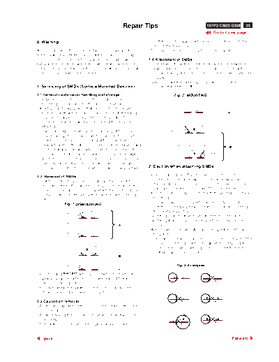
>> Download 25gs3-p35(RepairTip) documenatation <<
Text preview - extract from the document
                                                              Repair Tips                                              107P2 CM25 GSIII   35
                                                                                                                                          26
                                                                                                                          Go to cover page

0. Warning                                                               preferably be equipped with a thermal control (soldering
                                                                         temperature: 225 to 250 oC).
All ICs and many other semi-conductors are susceptible to             - The chip, once removed, must never be reused.
electrostatic discharges (ESD). Careless handling during
repair can reduce life drastically. When repairing, make sure         1.4 Attachment of SMDs
that you are connected with the same potential as the mass            - Locate the SMD on the solder lands by means of tweezers
of the unit via a wrist wrap with resistance. Keep components            and solder the component on one side. Ensure that the
and tools also at the same potential !                                   component is positioned correctly on the solder lands (see
                                                                         Fig.2A).
                                                                      - Next complete the soldering of the terminals of the
1. Servicing of SMDs (Surface Mounted Devices)                           component (see Fiq. 2B).

1.1 General cautions on handling and storage                                          Fig. 2 MOUNTING
- Oxidation on the terminals of SMDs results in poor
                                                                                           e.g. A PAIR OF TWEEZERS
   soldering. Do not handle SMDs with bare hands.
- Avoid using storage places that are sensitive to oxidation
   such as places with sulphur or chlorine gas, direct sunlight,                                                                 A
   high temperatures or a high degree of humidity. The
   capacitance or resistance value of the SMDs may be                                         SOLDER
                                                                                              0.5 - 0.8 mm
   affected by this.                                                              SOLDERING
                                                                                                             PRESURE

- Rough handling of circuit boards containing SMDs may                            IRON

   cause damage to the components as well as the circuit
   boards. Circuit boards containing SMDs should never be
   bent or flexed. Different circuit board materials expand and                      SOLDERING TIME       SOLDER
                                                                                                                                 B
                                                                                     < 3 sec/side         0.5 - 0.8 mm
   contract at different rates when heated or cooled and the                                      PRESURE

   components and/or solder connections may be damaged                                                               SOLDERING
                                                                                                                     IRON
   due to the stress. Never rub or scrape chip components as
   this may cause the value of the component to change.
   Similarly, do not slide the circuit board across any surface.      2. Caution when attaching SMDs

                                                                      - When soldering the SMD terminals, do not touch them
1.2 Removal of SMDs
                                                                         directly with the soldering iron. The soldering should be
- Heat the solder (for 2-3 seconds) at each terminal of the
                                                                         done as quickly as possible, care must be taken to avoid
   chip. By means of litz wire and a slight horizontal force,
                                                                         damage to the terminals of the SMDs themselves.
   small components can be removed with the soldering iron.
                                                                      - Keep the SMD's body in contact with the printed board when
   They can also be removed with a solder sucker (see Fig.
                                                                         soldering.
   1A)
                                                                      - The soldering iron to be used (approx. 30 W ) should
                Fig. 1 DISMOUNTING
                                                                         preferably be equipped with a thermal control (soldering
                                                                         temperature: 225 to 250 C).
                                                                                                    o
                                    VACUUM PISTON
                SOLDERING           4822 395 10159
                IRON                                                  - Soldering should not be done outside the solder land.
                e.g. WELLER                                           - Soldering flux (of rosin) may be used, but should not be
                SOLDER TIP PT -H7
                                                          A              acidic.
                                                                      - After soldering, let the SMD cool down gradually at room
               SOLDERING
               IRON                                                      temperature.
               SOLDER WICK                                            - The quantity of solder must be proportional to the size of the
               4822 321 40042
                                                                         solder land. If the quantity is too great, the SMD might
                           e.g. A PAIR OF TWEEZERS
                                                                         crack or the solder lands might be torn loose from the
                      HEATING                   HEATING                  printed board (see Fig. 3).
                                                          B

                SOLDERING                                                              Fig. 3 Examples
                IRON
                                                          C
- While holding SOLDER WICK with a pair of tweezers, take it off
                  the SMD
   gently using the soldering iron's heat applied to each
   terminal (see Fig. 1 B).                                                            RIGHT

- Remove the excess solder on the solder lands by means of
   litz wire or a solder sucker (see Fig. 1C).

1.3 Caution on removal
- When handling the soldering.iron. use suitable pressure and
   be careful.                                                                      SOLDERING
                                                                                    IRON
- When removing the chip, do not use undue force with the
   pair of tweezers.
- The soldering iron to be used (approx. 30 W) should


   Back                                                                                                                              Forward
◦ Jabse Service Manual Search 2026 ◦ Jabse Pravopis ◦ onTap.bg ◦ Other service manual resources online : Fixya ◦ eServiceinfo