Service Manuals, User Guides, Schematic Diagrams or docs for : Philips Monitor CD 2001 Monitor CD 2001 E-MANUALS Philips crt 107s2 PDF 107s2-p14
<< Back | HomeMost service manuals and schematics are PDF files, so You will need Adobre Acrobat Reader to view : Acrobat Download Some of the files are DjVu format. Readers and resources available here : DjVu Resources
For the compressed files, most common are zip and rar. Please, extract files with Your favorite compression software ( WinZip, WinRAR ... ) before viewing. If a document has multiple parts, You should download all, before extracting.
Good luck. Repair on Your own risk. Make sure You know what You are doing.
Image preview - the first page of the document
>> Download 107s2-p14 documenatation <<
Text preview - extract from the document
 14     107S2 CM23 GS III                          Mechanical Instructions
9 Go to cover page
0. General
To be able to perform measurements and repairs on the "circuit
boards", these unit should placed in the service position first.
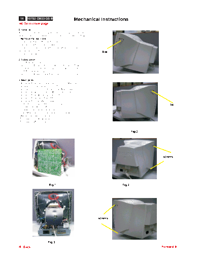
1.Remove the rear cover
-Remove right and left lib on the back cover
-Open 4 lids with "-" type screwdriver.
-Remove 4 screws at the bottom cabinet with "+" type
 screwdriver,refer fig 2.
                                                                     lids
-Remove out back cover.

2. Video panel
a.Cutoff all wire cable ties
b.Remove GRD wire between video shield and CRT rack.
c.Remove 1 screw between mains board rack and video shield
d. cutoff 1 cable tie on LOT wire
e.Remove GRD wire (1604)from video PCB to CRT rack.

3. Main panel
- Disconnect the degaussing coil (1113)from Main panel.
- Remove the video panel from CRT.
- Remove the "screw" of I/F cable from Main panel.
- Disconnect the CRT ground "M312" from Video panel.
- Disconnect the Hi-Pot cap from CRT.
- Disconnect yoke wire from "M401".
- Disconnect concellation connector(1402).
- Slide the main panel out of bottom tray.                                                       lid
- Connect yoke wire to "M401".
- Connect concellation connector(1402).".
- Place Main panel in service position as shown in Fig.1.
- Mount Video panel again on CRT.
- To connect Hi-Pot cap again.
- To connect "M312" again.


                                                                                    Fig.2


                                                                                            screws


                            Fig.1                                           Fig.3


                                                                   screws


                           Fig.3
    Back                                                                                    Forward
◦ Jabse Service Manual Search 2026 ◦ Jabse Pravopis ◦ onTap.bg ◦ Other service manual resources online : Fixya ◦ eServiceinfo